How to Calculate Resistance in a Series Circuit (Formula, Steps & Examples) 2026
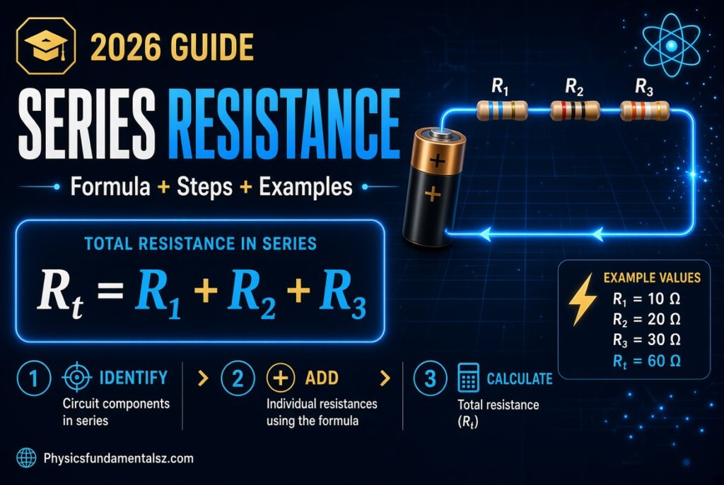
Need the total resistance of resistors wired end to end? Add their values together. That one rule is the core of how to calculate resistance in a series circuit.
Table of Contents
How to Calculate Resistance in a Series Circuit? The Series Resistance Formula
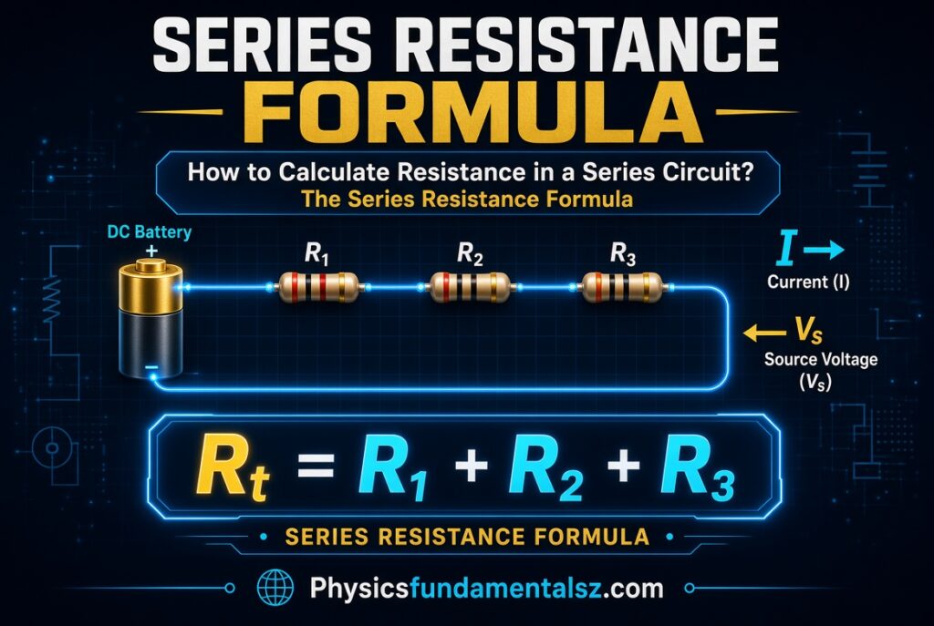
Definition: In a series circuit, the total (equivalent) resistance equals the sum of all individual resistances.
R_total = R₁ + R₂ + R₃ + … + Rₙ
Example: 10 Ω + 22 Ω + 47 Ω = 79 Ω.
Convert every value to the same unit before adding. Ohms (Ω) are the standard choice.
Key Takeaways
- Series resistances add directly, so the total is always larger than the biggest resistor.
- The same current flows through every resistor in the chain.
- The source voltage divides among the resistors in proportion to their values.
- Use Ohm’s law (V = I × R) to find current and voltage drops once you know R_total.
- Always convert kΩ and MΩ to ohms before adding.
What Is a Series Circuit?
A series circuit connects components one after another along a single path. Charge has nowhere else to go, so it passes through every component in turn.
One Path for Current
Picture a garden hose with several narrow sections joined in a row. All the water must pass through each section. Electric current behaves the same way in a series circuit.
Same Current, Shared Voltage
Current is identical at every point in the loop. Voltage is different. Each resistor uses up part of the battery’s voltage, and those parts add up to the supply voltage.
Why Resistance Adds Up
Resistance depends on a conductor’s length, cross-section and material. Joining resistors end to end works like making one longer conductor.
A longer path means more opposition to current, so the values simply add.
Series Resistance Formula Explained
The formula works for any number of resistors. Two resistors give R₁ + R₂. Ten resistors give R₁ + R₂ + … + R₁₀.
Symbols and Units
| Symbol | Meaning | Unit |
|---|---|---|
| R_total (or R_eq) | Equivalent resistance of the whole series string | ohm (Ω) |
| R₁, R₂, … Rₙ | Individual resistor values | ohm (Ω) |
| V | Source voltage | volt (V) |
| I | Circuit current | ampere (A) |
| P | Power | watt (W) |
Resistance Unit Conversions
| Unit | Equals | Example |
|---|---|---|
| 1 Ω | 1 Ω | 470 Ω |
| 1 kΩ (kilohm) | 1,000 Ω | 4.7 kΩ = 4,700 Ω |
| 1 MΩ (megohm) | 1,000,000 Ω | 0.1 MΩ = 100,000 Ω |
How to Calculate Resistance in a Series Circuit Step by Step
Follow these five steps for any series resistor circuit.
Step 1: Confirm the Resistors Are Truly in Series
Trace the current path. Resistors are in series only if the same current must pass through each one. If a wire branches off between two resistors, they are not in series.
Step 2: List Every Resistance Value
Write down R₁, R₂, R₃ and so on. Read the values from the schematic, the resistor color bands or a multimeter.
Step 3: Convert to the Same Unit
Change kΩ and MΩ values into ohms. For example, 2.2 kΩ becomes 2,200 Ω.
Step 4: Add the Values
Apply R_total = R₁ + R₂ + R₃ + … + Rₙ. Keep the units consistent as you add.
Step 5: Sanity-Check the Answer
The total must be larger than your biggest single resistor. If it is smaller, you probably used the parallel formula by mistake.
How to Read Resistor Values Before You Add Them

Most through-hole resistors use color bands. The first two bands give digits, the third is a multiplier and the fourth is tolerance.
| Color | Digit | Multiplier |
|---|---|---|
| Black | 0 | ×1 |
| Brown | 1 | ×10 |
| Red | 2 | ×100 |
| Orange | 3 | ×1,000 |
| Yellow | 4 | ×10,000 |
| Green | 5 | ×100,000 |
| Blue | 6 | ×1,000,000 |
| Violet | 7 | ×10,000,000 |
| Gray | 8 | ×100,000,000 |
| White | 9 | ×1,000,000,000 |
Gold means ±5% tolerance and silver means ±10%. A brown-black-red-gold resistor is 10 × 100 = 1,000 Ω (1 kΩ) at ±5%.
Worked Examples: Calculating Series Resistance
Example 1: Three Resistors in Series
Find the total resistance of 10 Ω, 22 Ω and 47 Ω resistors in series.
R_total = 10 + 22 + 47 = 79 Ω
The answer is larger than 47 Ω, so it passes the sanity check.
Example 2: Kilohm Resistors With a 9 V Battery
Three resistors of 3 kΩ, 10 kΩ and 5 kΩ sit in series with a 9 V battery.
R_total = 3 + 10 + 5 = 18 kΩ (18,000 Ω)
Current: I = V ÷ R = 9 V ÷ 18,000 Ω = 0.5 mA
Example 3: Mixed Units
Add 470 Ω, 1.5 kΩ and 2.2 kΩ.
Convert first: 470 Ω + 1,500 Ω + 2,200 Ω = 4,170 Ω, or 4.17 kΩ.
Adding 470 + 1.5 + 2.2 directly would give a meaningless number.
Example 4: Finding a Missing Resistor
A 9 V source drives 0.25 A through R₁ = 12 Ω, R₂ = 8 Ω and an unknown R₃.
First find the total: R_total = V ÷ I = 9 ÷ 0.25 = 36 Ω.
Then subtract: R₃ = 36 − 12 − 8 = 16 Ω.
Example 5: Identical Resistors Shortcut
When all resistors match, multiply instead of adding. Six 33 Ω resistors in series give:
R_total = n × R = 6 × 33 = 198 Ω
Example 6: Building a Non-Standard Value
You need about 150 Ω for an LED on a 5 V supply. Assume the LED drops 2 V at 20 mA.
Required resistance: R = (5 − 2) ÷ 0.020 = 150 Ω.
If you lack a 150 Ω part, join 100 Ω and 47 Ω in series for 147 Ω. The current becomes 3 ÷ 147 ≈ 20.4 mA, which is close enough.
Using Ohm’s Law With Series Resistance
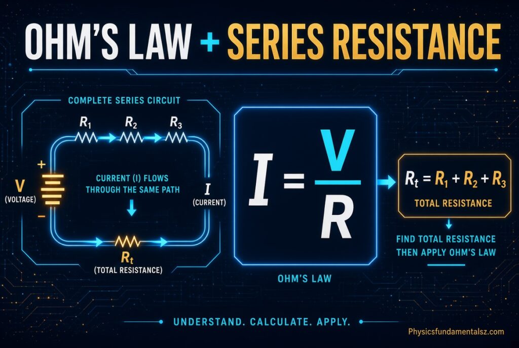
Once you know R_total, Ohm’s law unlocks everything else. Use it for current, voltage drops and power.
Finding the Circuit Current
Divide the supply voltage by R_total. In Example 1 with a 12 V battery: I = 12 ÷ 79 ≈ 0.152 A.
This same current flows through all three resistors.
Finding the Voltage Drop Across Each Resistor
Multiply the shared current by each resistor’s value.
| Resistor | Value | Current | Voltage drop (V = I × R) | Power (P = I²R) |
|---|---|---|---|---|
| R₁ | 10 Ω | 0.152 A | 1.52 V | 0.23 W |
| R₂ | 22 Ω | 0.152 A | 3.34 V | 0.51 W |
| R₃ | 47 Ω | 0.152 A | 7.14 V | 1.08 W |
| Total | 79 Ω | 0.152 A | 12.00 V | 1.82 W |
Checking With Kirchhoff’s Voltage Law
Kirchhoff’s voltage law says the voltage drops around a loop equal the source voltage. Here, 1.52 + 3.34 + 7.14 = 12.00 V. The numbers agree.
Calculating Total Power
Total power can be found three ways: P = V × I, P = I² × R_total or P = V² ÷ R_total. All give about 1.82 W here.
The total power dissipated in the resistors equals the power supplied by the source. That reflects conservation of energy.
The Voltage Divider Rule
A quick way to find one resistor’s share of the voltage: V_x = V_source × (R_x ÷ R_total).
With 12 V across a 10 kΩ and a 20 kΩ resistor, the 20 kΩ resistor gets 12 × 20 ÷ 30 = 8 V.
How to Measure Resistance in a Series Circuit With a Multimeter
You can confirm your calculation with a digital multimeter set to the ohms (Ω) range.
- Turn off and disconnect the power source completely.
- Set the multimeter to the ohms range.
- Touch the probes to the two outer ends of the series string.
- Read the display and compare it with your calculated R_total.
Measure with power off, or the reading will be wrong and the meter can be damaged. Also remember that other parts of the circuit connected across the string can distort the reading. Isolate the resistors if needed.
Series vs Parallel Resistance
| Feature | Series circuit | Parallel circuit |
|---|---|---|
| Current path | One single path | Multiple branches |
| Current | Same through every resistor | Splits among branches |
| Voltage | Divides among resistors | Same across every branch |
| Total resistance formula | R₁ + R₂ + … + Rₙ | 1/R_total = 1/R₁ + 1/R₂ + … + 1/Rₙ |
| Total vs individual | Larger than the biggest resistor | Smaller than the smallest resistor |
| If one component fails open | Whole circuit stops | Other branches keep working |
| Typical use | Current limiting, voltage dividers | Household outlets, lighting circuits |
Series-Parallel (Mixed) Circuits
Real circuits often combine both arrangements. Simplify them in stages. Reduce each obvious series group or parallel group to a single equivalent value, then repeat.
Example: R₁ = 100 Ω is in series with a parallel pair of 200 Ω and 300 Ω.
Parallel pair: (200 × 300) ÷ (200 + 300) = 120 Ω.
Total: 100 + 120 = 220 Ω.
Resistor Tolerance and Real-World Accuracy
Real resistors are not exact. A ±5% resistor can be off by 5% in either direction.
For Example 1 (79 Ω), the worst-case range with 5% parts is 79 × 0.95 = 75.05 Ω to 79 × 1.05 = 82.95 Ω.
Use 1% parts when precision matters, such as in voltage dividers for sensors. Series strings also average out some random error, since not every resistor is off in the same direction.
Battery Internal Resistance (Advanced)
Real batteries have a small internal resistance (r) that acts in series with your circuit.
The full current is I = V ÷ (R_total + r). With a 12 V battery, r = 0.5 Ω and R_total = 79 Ω, I = 12 ÷ 79.5 ≈ 0.151 A.
The terminal voltage falls to about 12 − (0.151 × 0.5) ≈ 11.92 V.
Do the Series Rules Apply to Other Components?
Not every component follows the same rule, so check before you add.
| Component in series | Rule |
|---|---|
| Resistors | Add: R_total = R₁ + R₂ + … |
| Inductors (no coupling) | Add: L_total = L₁ + L₂ + … |
| Capacitors | Reciprocals add: 1/C_total = 1/C₁ + 1/C₂ + … |
| Batteries (same direction) | Voltages add |
| Diodes and LEDs | Not fixed resistors, so use their forward voltage instead |
Real-World Uses of Series Resistance
- LED current limiting: A series resistor keeps current at a safe level.
- Voltage dividers: Two series resistors scale a voltage down for sensors and microcontrollers.
- Fuses, switches and breakers: They sit in series with a load so they can interrupt the current.
- Ammeters: They connect in series so the full circuit current passes through them.
- Custom resistor values: Two or more standard parts combine to hit a value you cannot buy off the shelf.
Common Mistakes to Avoid
| Mistake | Why it is wrong | Fix |
|---|---|---|
| Using the parallel (reciprocal) formula | It gives a total smaller than any resistor | Simply add the values in series |
| Mixing kΩ and Ω | The sum is off by a factor of 1,000 | Convert everything to ohms first |
| Using total voltage with one resistor’s value | The result matches nothing real in the circuit | Use V_total with R_total, or V_R with R |
| Measuring with power on | Gives false readings and can damage the meter | Disconnect power first |
| Ignoring tolerance | The real value can differ from the label | Check the tolerance band |
| Forgetting battery internal resistance | Predicted current is slightly too high | Add r to R_total when accuracy matters |
| Assuming parts are in series when a branch exists | Current is not the same through both parts | Trace the path and look for junctions |
Expert Tips
- Estimate the answer first by rounding. If the total looks wrong, recheck your units.
- Label every resistor and write its value in ohms before you add.
- Use a series resistor calculator to double-check hand calculations, but understand the method too.
- Check power ratings. In series, each resistor carries the same current, so the biggest resistor dissipates the most heat.
- Keep a common-values table (E12 or E24 series) handy when combining resistors to hit a target.
Practice Problems
Try these, then check the answers below.
- Find R_total for 100 Ω, 220 Ω and 330 Ω in series.
- Find R_total for 1.2 kΩ, 4.7 kΩ and 680 Ω in series.
- A 12 V battery drives current through a total series resistance of 600 Ω. What is the current?
- The measured total is 48 Ω. R₁ = 18 Ω and R₂ = 12 Ω. Find R₃.
- Five identical 68 Ω resistors are in series. What is R_total?
Answers
- 650 Ω
- 1,200 + 4,700 + 680 = 6,580 Ω (6.58 kΩ)
- I = 12 ÷ 600 = 0.02 A (20 mA)
- R₃ = 48 − 18 − 12 = 18 Ω
- 5 × 68 = 340 Ω
Also Read:
- Ohm’s Law Calculator: Solve for Current
- Physics Fundamentals: The Complete Guide to Core Concepts, Laws, and Equations
- Play Physics Games (Build Circuits and More)
- Momentum Calculator Physics: Formula, Steps & Worked Examples
- Difference Between Speed and Velocity With Examples
- Kinetic Energy
- Angular Momentum
- Tension Force
- The Doppler Effect
- Newton’s Laws of Motion
- Conservation of Momentum
- Momentum and Impulse
- Work Done in Physics
- Power in Physics
- Torque in Physics
- Friction Force Explained
- Hooke’s Law and Springs
- Simple Harmonic Motion
- Circular Motion and Centripetal Force
- Wave Speed, Frequency & Wavelength
- Speed of Light: The Ultimate Guide to c, the Cosmic Speed Limit
Frequently Asked Questions (FAQs)
What is the formula for resistance in a series circuit?
R_total = R₁ + R₂ + R₃ + … + Rₙ. Add every resistor’s value, using the same unit for all of them.
How do you find total resistance in a series circuit with 3 resistors?
Add the three values. For 10 Ω, 22 Ω and 47 Ω, the total is 79 Ω.
Why does resistance add up in a series circuit?
Charge must pass through every resistor in turn. Each one adds its own opposition, much like lengthening a single conductor.
Is total resistance bigger or smaller in a series circuit?
It is bigger. The total is always greater than the largest individual resistor.
How do you calculate resistance in a series circuit with voltage and current?
Use Ohm’s law rearranged: R_total = V ÷ I. If a 9 V source drives 0.25 A, the total is 36 Ω.
Is current the same everywhere in a series circuit?
Yes. There is only one path, so the same current flows through every component.
How do you find the voltage across each resistor in series?
Multiply the shared current by each resistor’s value (V = I × R). You can also use the voltage divider rule.
What happens to total resistance when you add another resistor in series?
The total increases by exactly that resistor’s value. Current from a fixed voltage source then drops.
How do you calculate series resistance with different units?
Convert all values to ohms first. For example, 2.2 kΩ becomes 2,200 Ω before you add it to any ohm values.
What is the difference between series and parallel resistance?
In series, resistances add and the current is shared. In parallel, reciprocals add and the voltage is shared, so the total is smaller than any branch.
Can I use the series resistance formula for capacitors?
No. Capacitors in series follow a reciprocal rule: 1/C_total = 1/C₁ + 1/C₂ + …. Inductors in series do add, like resistors.
How do you find a missing resistor in a series circuit?
Find R_total from V ÷ I, then subtract the known resistors. The remainder is the unknown value.
How many resistors can you connect in series?
There is no theoretical limit. In practice, the supply voltage and power ratings decide how many make sense.
What is equivalent resistance?
It is the single resistor value that would draw the same current from the same source as the whole combination.
How do you measure resistance in a series circuit?
Turn the power off, set a multimeter to ohms and measure across the two ends of the series string.
Does wire resistance matter in a series circuit?
Usually not. Connecting wires have far less resistance than the load, so they are treated as ideal in most calculations.
What happens if one resistor fails open in a series circuit?
The circuit is broken, current stops and every component in the loop goes off.
How do you calculate power in a series circuit?
Use P = V × I for the total, or P = I² × R for each resistor. The individual powers add up to the total.
How do you calculate resistance in a series-parallel circuit?
Reduce each parallel group to one equivalent value, then add the series parts. Repeat until one value remains.
Do identical resistors in series share voltage equally?
Yes. Equal resistances carry the same current, so each drops the same voltage: V_source ÷ n.
Why are household outlets wired in parallel instead of series?
Parallel wiring gives every appliance the full supply voltage. Each device also works independently of the others.
Conclusion
To calculate resistance in a series circuit, convert all values to ohms and add them. The result is always larger than your biggest resistor.
From there, Ohm’s law gives you the current, each voltage drop and the power. Checking that the drops add up to the supply voltage confirms your work.
Practice with the problems above, then test yourself using the Ohm’s Law Calculator and explore the rest of the site to keep building your physics skills.