How to Find Equivalent Capacitance in Series and Parallel: Formulas, Steps, and Solved Examples 2026
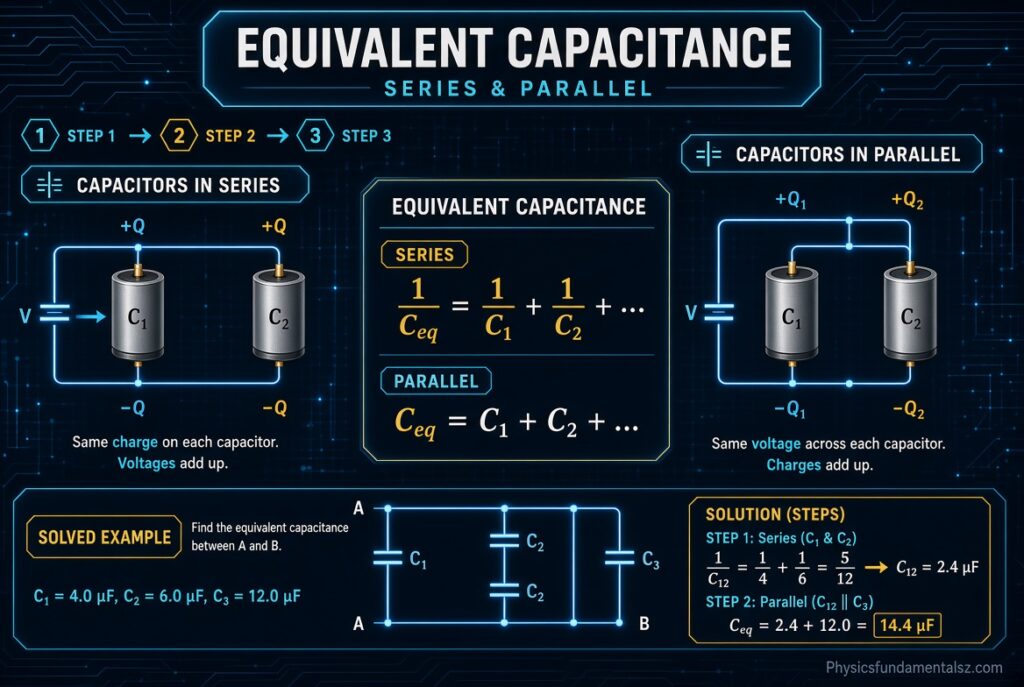
To find equivalent capacitance in series and parallel, you replace a group of capacitors with one single capacitor that stores the same charge at the same voltage. For capacitors in parallel you simply add the values. For capacitors in series you add the reciprocals and then flip the result.
How to Find Equivalent Capacitance in Series and Parallel? Equivalent capacitance, also called total capacitance or net capacitance, is the capacitance of that one imaginary replacement capacitor. It lets you simplify a crowded circuit into a single value you can use for charge, voltage, energy, and time constant calculations.
The rules look almost backwards if you already know resistors. Capacitors in parallel behave like resistors in series, and capacitors in series behave like resistors in parallel. Once you understand why, the formulas stop feeling like something to memorize.
Table of Contents
What Is Equivalent Capacitance? How to Find Equivalent Capacitance in Series and Parallel?
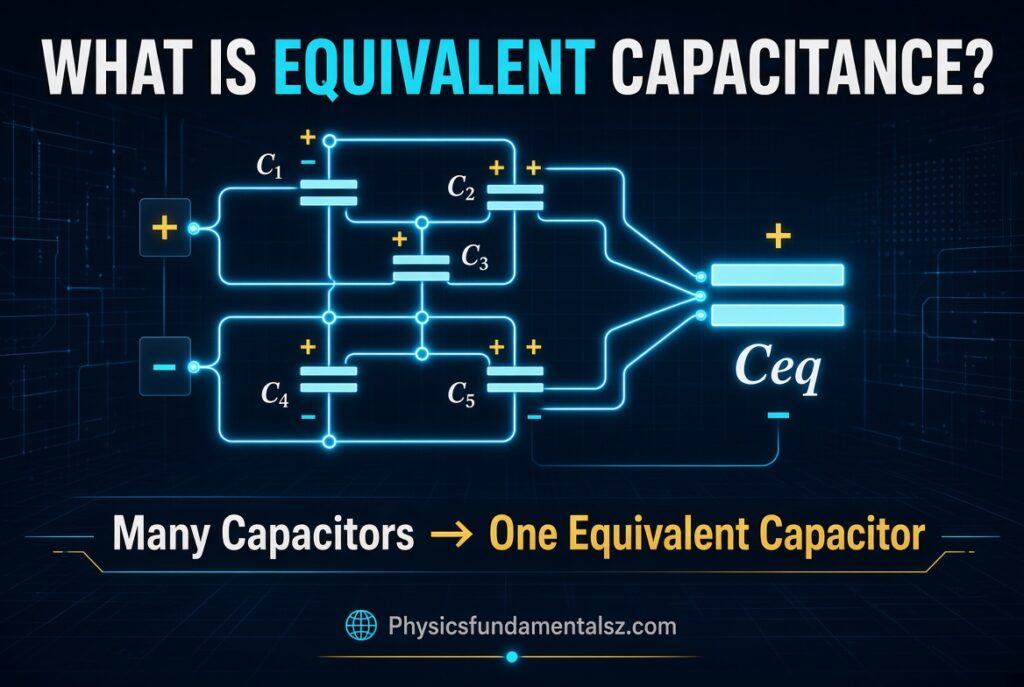
Equivalent capacitance is the single capacitance value that can replace a combination of capacitors without changing how the circuit behaves from the outside. The replacement capacitor holds the same total charge when the same voltage is applied across the same two terminals.
The idea is the same as equivalent resistance. You are not changing the circuit. You are describing it in a simpler way.
Equivalent Capacitance Definition
Formally, the equivalent capacitance is the ratio of the total charge delivered by the source to the voltage applied across the whole network: Ceq = Qtotal / Vtotal.
This definition works for any network, however complicated. Series and parallel formulas are just shortcuts that come from applying this definition to two simple layouts.
Equivalent Capacitance vs Total Capacitance vs Net Capacitance
These three phrases mean the same thing. Textbooks usually say equivalent capacitance. Electronics articles often say total capacitance. Some courses say net capacitance.
Whatever name you see, the goal is identical: one value that represents the entire combination between two terminals.
Why Equivalent Capacitance Matters
Real circuits rarely use a single capacitor. Designers combine capacitors to reach a value that is not sold as a standard part, to raise the voltage rating, to share ripple current, or to tune a filter.
Students meet the same idea in exams. Nearly every capacitor problem in introductory physics starts with reducing a network to one equivalent capacitor.
Capacitance Basics You Need Before Combining Capacitors
A short review of capacitance makes the series and parallel rules much easier to understand. If you already know this, skim the formulas and move on.
What Is Capacitance?
Capacitance measures how much electric charge a capacitor stores per volt applied across it. The defining equation is C = Q / V, where C is capacitance, Q is charge, and V is voltage.
A larger capacitance means the capacitor holds more charge at the same voltage.
Units of Capacitance: Farad, Microfarad, Nanofarad, Picofarad
The SI unit of capacitance is the farad (F). One farad equals one coulomb per volt. A farad is a huge amount, so most practical capacitors use smaller units.
| Unit | Symbol | Value in Farads |
|---|---|---|
| Millifarad | mF | 10⁻³ F |
| Microfarad | μF | 10⁻⁶ F |
| Nanofarad | nF | 10⁻⁹ F |
| Picofarad | pF | 10⁻¹² F |
Always convert every capacitor to the same unit before you add or take reciprocals. Mixing nF and μF is one of the most common sources of wrong answers.
What Determines Capacitance?
For a parallel-plate capacitor, capacitance is C = κε₀A / d. Here A is the plate area, d is the gap between the plates, κ is the dielectric constant, and ε₀ is the permittivity of free space, about 8.854 × 10⁻¹² F/m.
More plate area raises capacitance. A wider gap lowers it. A better dielectric material raises it.
This single formula explains the whole topic. Parallel connections effectively add area. Series connections effectively add gap. You will see this in detail in the derivation section.
What Does a Capacitor Do in a Circuit?
A capacitor stores energy in an electric field. It charges when voltage is applied and releases that energy when the circuit needs it.
Capacitors smooth power supply ripple, block DC while passing AC, couple signals between amplifier stages, set timing in RC circuits, and tune radio frequency circuits.
Equivalent Capacitance Formula for Series and Parallel Connections
Here is the full reference table. Keep this one handy for homework, exams, and circuit design.
| Connection | Formula | Total vs Individual Values | Same Quantity Across Each Capacitor | Quantity That Adds Up |
|---|---|---|---|---|
| Parallel | Ceq = C₁ + C₂ + C₃ + … | Larger than the largest | Voltage | Charge |
| Series | 1/Ceq = 1/C₁ + 1/C₂ + 1/C₃ + … | Smaller than the smallest | Charge | Voltage |
| Two in series | Ceq = (C₁ × C₂) / (C₁ + C₂) | Smaller than the smaller one | Charge | Voltage |
| Three in series | Ceq = C₁C₂C₃ / (C₁C₂ + C₂C₃ + C₁C₃) | Smaller than the smallest | Charge | Voltage |
| N equal in series | Ceq = C / N | N times smaller | Charge | Voltage |
| N equal in parallel | Ceq = N × C | N times larger | Voltage | Charge |
Parallel Formula
When capacitors share the same two nodes, the equivalent capacitance is the plain sum: Ceq = C₁ + C₂ + C₃ + … + Cₙ.
Adding a capacitor in parallel always increases the total.
Series Formula
When capacitors are chained one after another with no branches between them, the reciprocal of the equivalent capacitance equals the sum of the reciprocals: 1/Ceq = 1/C₁ + 1/C₂ + … + 1/Cₙ.
After you add the reciprocals, remember to take the reciprocal of the sum. Forgetting that last step is the most frequent error.
Memory Trick
Think of the formulas as the mirror image of resistors. For resistors, series adds directly. For capacitors, parallel adds directly.
Another quick check: series makes the total smaller, parallel makes it bigger. If your answer breaks that rule, something went wrong.
Capacitors in Series
Capacitors are in series when they are connected end to end in a single path, so the only way for current to travel from one to the next is straight through. There are no branch points between them.
How to Recognize a Series Connection
Look for a chain where the right plate of one capacitor connects only to the left plate of the next. If you trace the path and every capacitor sits on the same single route, they are in series.
If the wire splits between two capacitors, they are not in series, even if they look lined up on the page.
Key Properties of Capacitors in Series
Three facts describe every series combination.
- The same charge Q sits on every capacitor.
- The total voltage equals the sum of the individual voltages: V = V₁ + V₂ + V₃.
- The equivalent capacitance is smaller than the smallest capacitor.
The charge is equal because the conductors between neighboring capacitors are isolated. They start neutral, so whatever charge leaves one plate must appear on the next.
Total Capacitance of Capacitors in Series
Start from the voltage rule. Since V = V₁ + V₂ + V₃ and each V = Q / C, you get Q/Ceq = Q/C₁ + Q/C₂ + Q/C₃.
Cancel Q from every term. What remains is the series formula: 1/Ceq = 1/C₁ + 1/C₂ + 1/C₃.
Solved Example 1: Three Capacitors in Series
Find the equivalent capacitance of 1 μF, 5 μF, and 8 μF capacitors connected in series.
Step 1: Write the formula. 1/Ceq = 1/1 + 1/5 + 1/8.
Step 2: Add the reciprocals. 1 + 0.2 + 0.125 = 1.325 μF⁻¹.
Step 3: Flip the result. Ceq = 1 / 1.325 ≈ 0.755 μF.
The answer is below 1 μF, the smallest capacitor, which confirms the series rule.
Solved Example 2: Two Capacitors in Series
Two capacitors of 10 μF and 15 μF are in series. Use the product-over-sum shortcut.
Ceq = (10 × 15) / (10 + 15) = 150 / 25 = 6 μF.
The result is smaller than 10 μF, so the answer is reasonable.
Equal Capacitors in Series
When N identical capacitors are in series, the equivalent capacitance is simply C divided by N. Three 30 μF capacitors in series give 10 μF.
This shortcut is very handy when you build a lower value out of identical parts.
Voltage Division Across Series Capacitors
In a series string, the smaller capacitor takes the larger share of the voltage. This is the opposite of what many beginners expect.
For two capacitors, V₁ = V × C₂ / (C₁ + C₂) and V₂ = V × C₁ / (C₁ + C₂). Notice that each voltage depends on the other capacitor.
Why Series Capacitance Decreases
Think of two capacitors in series as one capacitor with a thicker gap between the plates. A wider gap means a weaker electric field per volt, so less charge is stored.
That is why adding more capacitors in series always lowers the total capacitance.
Capacitors in Parallel
Capacitors are in parallel when all of their top plates connect to one common node and all of their bottom plates connect to another. Every capacitor sees the same two nodes.
How to Recognize a Parallel Connection
Trace the wires. If both terminals of one capacitor connect directly to both terminals of another, they are in parallel.
A ladder-style layout where each capacitor sits on its own rung between two rails is the classic picture.
Key Properties of Capacitors in Parallel
- The same voltage appears across every capacitor.
- The total charge equals the sum of the individual charges: Q = Q₁ + Q₂ + Q₃.
- The equivalent capacitance is larger than the largest capacitor.
Voltage is shared because the same two nodes connect every capacitor. Each one stores charge independently.
Total Capacitance of Capacitors in Parallel
Start from the charge rule. Q = Q₁ + Q₂ + Q₃, and each Q = C × V. So Ceq × V = C₁V + C₂V + C₃V.
Cancel V and you get the parallel formula: Ceq = C₁ + C₂ + C₃.
Solved Example 3: Three Capacitors in Parallel
Find the net capacitance of 1 μF, 5 μF, and 8 μF capacitors in parallel.
Ceq = 1 + 5 + 8 = 14 μF.
Compare this with Example 1. The same three parts give 0.755 μF in series and 14 μF in parallel, a huge difference.
Solved Example 4: Parallel Capacitors With Mixed Units
Find the total capacitance of 2.2 μF, 470 nF, and 100 nF in parallel.
First convert everything to microfarads: 470 nF = 0.47 μF and 100 nF = 0.1 μF.
Then add: Ceq = 2.2 + 0.47 + 0.1 = 2.77 μF.
Equal Capacitors in Parallel
N identical capacitors in parallel give N times the capacitance. Four 25 μF capacitors in parallel make 100 μF.
Designers often use this trick to reach a large value or to lower total equivalent series resistance.
Charge Distribution in Parallel Capacitors
Because the voltage is the same, the larger capacitor stores more charge. A 10 μF capacitor holds twice as much charge as a 5 μF capacitor at the same voltage.
The charge splits in direct proportion to capacitance.
Why Parallel Capacitance Increases
Parallel capacitors act like one capacitor with a larger plate area. More area gives the charge more room to spread out, so more charge is stored at the same voltage.
This explains why the plain sum is the right rule.
Capacitance in Series and Parallel Combinations: Key Differences
Seeing both layouts side by side makes the contrast clear. Use this table to compare them at a glance.
| Feature | Series | Parallel |
|---|---|---|
| Formula | 1/Ceq = Σ(1/C) | Ceq = ΣC |
| Equivalent capacitance | Less than the smallest | More than the largest |
| Charge on each capacitor | Same | Different (proportional to C) |
| Voltage across each capacitor | Different (inversely proportional to C) | Same |
| Effect on total voltage rating | Can increase it (with care) | Limited by the lowest rating |
| Effect on energy storage at the same source voltage | Less energy stored | More energy stored |
| Behaves like resistors in | Parallel | Series |
| Typical use | Raising voltage capability, reducing capacitance | Increasing capacitance, filtering |
When to Use Series Capacitors
Choose series when you need a smaller capacitance than you have available, or when you need to divide a high voltage across several parts.
Series strings are also used in high-voltage supplies and in supercapacitor banks, where each cell has a low voltage limit.
When to Use Parallel Capacitors
Choose parallel when you need more capacitance, more energy storage, or lower impedance in power supply decoupling.
Parallel groups of different values also help filter a wider range of frequencies.
Capacitors vs Resistors: Why the Rules Look Reversed
The reversal comes from what each component stores or resists. Resistance opposes current. Capacitance stores charge per volt, so a larger capacitance is the opposite of a larger opposition.
| Network | Resistors | Capacitors |
|---|---|---|
| Series | Req = R₁ + R₂ + … | 1/Ceq = 1/C₁ + 1/C₂ + … |
| Parallel | 1/Req = 1/R₁ + 1/R₂ + … | Ceq = C₁ + C₂ + … |
| Key quantity in series | Same current | Same charge |
| Key quantity in parallel | Same voltage | Same voltage |
If you can solve a resistor network, you can solve a capacitor network by swapping the two formulas.
Capacitors vs Inductors
Inductors follow the resistor rules. Series inductors add, and parallel inductors use the reciprocal rule, assuming no mutual coupling.
So capacitors are the odd one out. They are the only common component where parallel is the simple sum.
How to Find Equivalent Capacitance of a Circuit Step by Step
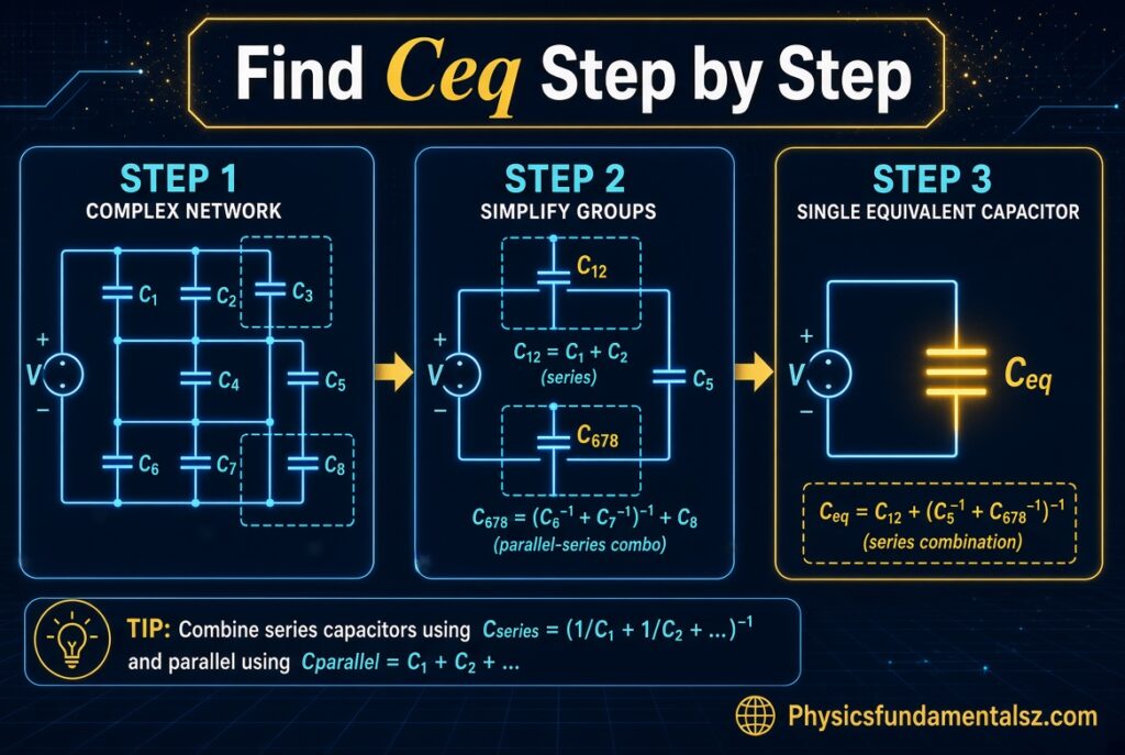
Real problems rarely show a clean series or parallel layout. This method works for any network that can be reduced with series and parallel rules.
Step 1: Identify the Two Terminals
Decide between which two points you want the equivalent capacitance. The answer depends on those terminals. The same network can have different equivalent values between different pairs of nodes.
Mark the terminals clearly before you start.
Step 2: Redraw the Circuit Neatly
Redraw the network so wires lie flat and nodes are obvious. Give every node with the same wire a single label.
A messy diagram hides parallel connections. Many mistakes disappear after a clean redraw.
Step 3: Find the Simplest Series or Parallel Group
Look for two or three capacitors that are clearly in series or clearly in parallel. Start with the group that is easiest to see.
Do not try to reduce everything at once.
Step 4: Replace the Group With Its Equivalent
Calculate the equivalent capacitance of that group and draw a single capacitor in its place. Write the new value on the diagram.
Keep track of the original capacitors you removed. You will need them later to find individual charges and voltages.
Step 5: Repeat Until One Capacitor Remains
Redraw and repeat. Each pass reduces the number of capacitors by at least one. Stop when a single equivalent capacitor sits between the two terminals.
Step 6: Check the Result
Run two quick sanity checks. Is the total smaller than the smallest capacitor if everything was in series? Is it bigger than the biggest capacitor if everything was in parallel?
For mixed networks, confirm that the answer lies in a reasonable range.
Series and Parallel Combination of Capacitors
Most textbook problems mix both connections. The trick is to reduce the network in layers, working from the inside out.
Solved Example 5: Series Branch in Parallel With a Capacitor
A 4 μF and a 12 μF capacitor are in series. That pair is connected in parallel with a 5 μF capacitor. Find the equivalent capacitance.
Step 1: Reduce the series pair. Ceq(series) = (4 × 12) / (4 + 12) = 48 / 16 = 3 μF.
Step 2: Add the parallel capacitor. Ceq = 3 + 5 = 8 μF.
The final answer is 8 μF.
Solved Example 6: Parallel Group in Series With a Capacitor
A 6 μF and a 3 μF capacitor are in parallel. That group is in series with an 18 μF capacitor. Find the equivalent capacitance.
Step 1: Reduce the parallel group. 6 + 3 = 9 μF.
Step 2: Combine with the series capacitor. Ceq = (9 × 18) / (9 + 18) = 162 / 27 = 6 μF.
The final answer is 6 μF.
Solved Example 7: A Longer Chain of Reductions
Take a 2 μF capacitor in series with a parallel pair of 3 μF and 5 μF. That whole branch sits in parallel with a 4 μF capacitor.
Step 1: Parallel pair: 3 + 5 = 8 μF.
Step 2: Series with 2 μF: (2 × 8) / (2 + 8) = 16 / 10 = 1.6 μF.
Step 3: Parallel with 4 μF: 1.6 + 4 = 5.6 μF.
The equivalent capacitance of the full network is 5.6 μF.
Which Should You Reduce First: Series or Parallel?
There is no fixed rule. Always reduce whichever group is clearly series or clearly parallel in the diagram you have in front of you.
If the circuit has a long ladder shape, start at the far end from the terminals and work back toward them.
Spotting Hidden Parallel and Series Connections
Two capacitors can look separated on the page yet connect to the same two nodes. They are in parallel. Redrawing with node labels reveals this quickly.
Likewise, if a node touches only two capacitors and nothing else, those two are in series. A third wire at that node breaks the series connection.
Equivalent Capacitance Between Two Points
The equivalent capacitance of a network depends on which two points you measure across. Every problem should state the terminals, usually A and B.
Why the Choice of Terminals Matters
Capacitors that are not in the current path between A and B can be ignored. A capacitor connected at only one end, with its other end floating, carries no charge and has no effect.
Always check that each capacitor really lies between the two terminals.
Shorted Capacitors
If a wire connects both plates of a capacitor, the voltage across it is zero. It stores no charge and can be removed from the calculation.
Spotting a shorted capacitor can turn a scary-looking network into an easy one.
Example: A Capacitor Shorted Out
A 6 μF capacitor is in series with a parallel combination of a 3 μF capacitor and a 9 μF capacitor. A wire shorts across the 9 μF capacitor.
The short bypasses the whole parallel group, because it connects the same two nodes. Both the 3 μF and 9 μF capacitors carry no charge.
Only the 6 μF capacitor remains in the path, so Ceq = 6 μF.
Bridge, Delta, and Star Capacitor Networks
Some networks cannot be reduced with series and parallel rules alone. A common example is the five-capacitor bridge.
The Balanced Bridge Shortcut
Picture two series branches between A and B. The first branch has C₁ then C₂, and the second has C₃ then C₄. A fifth capacitor C₅ connects the middle node of the first branch to the middle node of the second.
If C₁/C₂ = C₃/C₄, the two middle nodes are at the same potential. No charge flows through C₅, so you can remove it.
After removal, each branch is a simple series pair, and the two branches are in parallel.
Worked Balanced Bridge Example
Let C₁ = 2 μF, C₂ = 4 μF, C₃ = 3 μF, C₄ = 6 μF, and C₅ = 10 μF. The ratios are 2/4 = 0.5 and 3/6 = 0.5, so the bridge is balanced.
Remove C₅. The first branch gives (2 × 4) / (2 + 4) = 1.333 μF. The second branch gives (3 × 6) / (3 + 6) = 2 μF.
The branches are in parallel, so Ceq = 1.333 + 2 = 3.333 μF.
Unbalanced Bridges
When the ratios are not equal, the middle capacitor carries charge and you cannot simplify the network with series and parallel rules alone.
In that case use a delta-star transformation or write charge conservation equations at the nodes.
Star to Delta Transformation for Capacitors
A star (Y) network of capacitors Ca, Cb, and Cc can be converted into an equivalent delta network. The capacitance between two terminals is the product of the two star capacitors touching them, divided by the sum of all three.
For example, Cab = (Ca × Cb) / (Ca + Cb + Cc). The same pattern gives Cbc and Cca.
Notice that the form differs from resistor transformations. Capacitors use reciprocal rules, so the pattern flips.
Node Analysis for Complex Networks
For networks that resist all shortcuts, apply Kirchhoff-style rules for capacitors. Write charge conservation at each isolated node and voltage loop equations around each loop.
Solving the resulting linear equations gives every node voltage, and from that every charge. Circuit simulators do this automatically.
Charge, Voltage, and Energy in Series and Parallel Combinations
Finding equivalent capacitance is usually only the first step. Many problems then ask for the charge, voltage, or energy on each capacitor.
Key Relationships
| Quantity | Formula |
|---|---|
| Capacitance | C = Q / V |
| Charge | Q = C × V |
| Energy stored | U = ½ C V² = ½ Q V = Q² / (2C) |
| Series rule | Same Q, voltages add |
| Parallel rule | Same V, charges add |
Solved Example 8: Series Capacitors Connected to a 12 V Battery
A 4 μF and a 12 μF capacitor are in series across a 12 V battery. Find the charge, voltage, and energy.
Step 1: Equivalent capacitance. Ceq = (4 × 12) / 16 = 3 μF.
Step 2: Total charge. Q = Ceq × V = 3 μF × 12 V = 36 μC. In a series string, each capacitor holds this same 36 μC.
Step 3: Voltage on each. V₁ = 36 / 4 = 9 V. V₂ = 36 / 12 = 3 V. They add to 12 V, as expected.
Step 4: Energy. U = ½ × 3 μF × 12² = 216 μJ. As a check, 162 μJ on the 4 μF capacitor plus 54 μJ on the 12 μF capacitor also equals 216 μJ.
Solved Example 9: Parallel Capacitors Connected to a 12 V Battery
A 4 μF, 6 μF, and 10 μF capacitor are in parallel across a 12 V battery.
Step 1: Equivalent capacitance. Ceq = 4 + 6 + 10 = 20 μF.
Step 2: Charges. Q₁ = 4 × 12 = 48 μC. Q₂ = 6 × 12 = 72 μC. Q₃ = 10 × 12 = 120 μC. The total is 240 μC, which equals 20 μF × 12 V.
Step 3: Energy. U = ½ × 20 μF × 12² = 1440 μJ, or 1.44 mJ.
Solved Example 10: Mixed Network at 10 V
A 4 μF and 12 μF capacitor in series are placed in parallel with a 5 μF capacitor. The source is 10 V.
The series branch has an equivalent of 3 μF, so its charge is 3 × 10 = 30 μC. This same 30 μC sits on both the 4 μF and 12 μF capacitors.
Their voltages are 30/4 = 7.5 V and 30/12 = 2.5 V, which add to 10 V. The 5 μF capacitor sees the full 10 V and holds 50 μC.
Total charge is 80 μC, and 80 μC / 10 V = 8 μF, matching Example 5.
Energy Stored: Series vs Parallel
At the same source voltage, a parallel combination stores more energy because its equivalent capacitance is larger. A series combination stores less.
If you connect the same two capacitors to the same battery, the parallel arrangement stores far more energy than the series arrangement.
Does Connecting Capacitors Change Total Energy?
When capacitors charged to different voltages are connected together, some energy is usually lost as heat or radiation in the connecting wires. Charge is conserved, but energy is not.
This surprises many students, and it appears in exam questions about redistributing charge.
Why the Equivalent Capacitance Formulas Work
Understanding the derivation lets you rebuild the formulas on the spot, even if you forget them.
Derivation for Parallel Capacitors
Each capacitor shares the same voltage V. The charges are Q₁ = C₁V, Q₂ = C₂V, and so on. The source supplies the sum of these charges.
So Qtotal = (C₁ + C₂ + …) V. Dividing by V gives Ceq = C₁ + C₂ + ….
Derivation for Series Capacitors
Each capacitor carries the same charge Q. The voltages are V₁ = Q/C₁, V₂ = Q/C₂, and so on. The source voltage equals their sum.
So V = Q (1/C₁ + 1/C₂ + …). Since Ceq = Q/V, taking the reciprocal gives 1/Ceq = 1/C₁ + 1/C₂ + ….
Geometric Explanation Using Plate Area and Separation
Recall C = κε₀A / d. Connecting plates in parallel is like gluing the plates side by side, which adds area. Capacitance rises.
Connecting capacitors in series stacks the gaps on top of each other, which adds distance. Capacitance falls.
Dimensional Check
Reciprocal capacitance has units of volts per coulomb. Voltages add in series, so reciprocal capacitances add in series. That matches the formula.
For parallel, charges add and charge per volt is capacitance, so capacitances add.
Capacitor Voltage Rating in Series and Parallel Combinations
Equivalent capacitance is only half the story when you build a real circuit. Every capacitor has a maximum voltage rating, and exceeding it can cause failure.
Voltage Rating in Parallel
In a parallel group, every capacitor sees the full applied voltage. The group is limited by the lowest voltage rating among its members.
A 50 V capacitor in parallel with a 16 V capacitor should never be used above 16 V.
Voltage Rating in Series
In an ideal series string of identical capacitors, the voltage splits equally, so the string can handle roughly the sum of the ratings. Two 25 V capacitors in series could, in theory, handle 50 V.
In practice, real capacitors have different leakage currents and tolerances. Voltage may not split evenly, and one capacitor can see more than its rating.
Why Voltage Divides Unevenly in Real Series Strings
With ideal capacitors, voltage division depends on capacitance. A capacitor with a lower real value takes a larger share of the voltage.
Tolerance of ±20% is common for electrolytic capacitors. A string that looks balanced on paper can be noticeably unbalanced once built.
Balancing Resistors
Designers add equal-value resistors across each capacitor in a series string. These resistors force the DC voltage to divide evenly, regardless of small differences in leakage current.
The resistor value should draw much more current than the leakage of the capacitors, but not so much that it wastes power. Datasheet leakage specifications guide this choice.
Supercapacitor Banks
Supercapacitor cells typically have low voltage limits. Engineers stack them in series to reach higher voltages and use balancing circuits to protect each cell.
The stack’s total capacitance follows the series rule, so it drops as cells are added.
Polarized Capacitors
Electrolytic and tantalum capacitors have a positive and negative terminal. When combining them, keep polarity consistent with the circuit voltage.
Reversing polarity can damage the capacitor and, in some types, cause failure with heat or venting.
Equivalent Capacitance Shortcuts and Tricks
A few quick habits save time on exams and in lab work.
Product Over Sum for Two Capacitors
For two capacitors in series, always use (C₁ × C₂) / (C₁ + C₂). It avoids fractions and is easy to check on a calculator.
If the two values are equal, the answer is exactly half of either one.
One Much Smaller Capacitor in Series
When one capacitor in a series string is much smaller than the others, the total is almost equal to that smallest value. The small capacitor dominates.
For example, 1 μF in series with 100 μF gives 0.99 μF, almost exactly 1 μF.
One Much Larger Capacitor in Parallel
When one capacitor in a parallel group is much larger than the rest, the total is only slightly larger than that big one. The small ones barely matter.
A 1000 μF capacitor in parallel with a 1 μF capacitor gives 1001 μF. The extra 1 μF changes the total by about 0.1%.
Build a Target Value From Standard Parts
Capacitors come in standard values like 1.0, 2.2, 4.7, and 10. If you need a value in between, combine parts.
- To make 14.7 μF, place 10 μF and 4.7 μF in parallel.
- To make 5 μF, place two 10 μF capacitors in series.
- To make 3.3 μF from 10 μF, place three 10 μF capacitors in series: 10 / 3 = 3.33 μF.
Quick Estimate With Ratios
If you need a fast estimate, round each value. Then check against the series and parallel rules. If the estimate and the precise answer disagree widely, recheck for an arithmetic slip.
Think in Reciprocals for Series
For long series chains, convert each capacitance to its reciprocal first. Add the reciprocals as plain numbers. Flip the result once at the end.
Doing the flip only once reduces rounding mistakes.
Common Mistakes When Finding Equivalent Capacitance
Most wrong answers come from a short list of habits. Watch for these.
Forgetting to Invert the Final Sum in Series
Students add the reciprocals correctly and then stop. The result is 1/Ceq, not Ceq. Always take the reciprocal at the end.
A good safeguard is to check that your final value is smaller than the smallest capacitor.
Using the Resistor Formulas by Habit
Capacitor rules are reversed. Parallel adds, and series uses reciprocals. Writing the formula down before calculating prevents the slip.
Mixing Units
Adding 470 nF to 2.2 μF without conversion gives nonsense. Convert every value to the same unit first.
Also remember that 1000 nF equals 1 μF, and 1000 pF equals 1 nF.
Misidentifying Series and Parallel
Two capacitors are in parallel only if both ends connect to the same two nodes. They are in series only if they share a node with nothing else attached.
Redraw the circuit and label the nodes. This clears up most confusion.
Ignoring Shorted or Floating Capacitors
A capacitor with a wire across it holds no charge. A capacitor connected at only one end does nothing. Remove both from the calculation.
Assuming Equal Voltage in Series
In series, the charge is equal, not the voltage. Unless the capacitors are identical, their voltages will differ.
Ignoring Voltage Ratings
A circuit may compute correctly on paper and still fail because one capacitor exceeds its rated voltage. Check ratings whenever you combine real parts.
Treating Energy as Conserved When Connecting Charged Capacitors
When you connect charged capacitors, charge is conserved but energy typically is not. Some energy turns into heat in the wires and connections.
Capacitance in AC Circuits: Reactance and Impedance
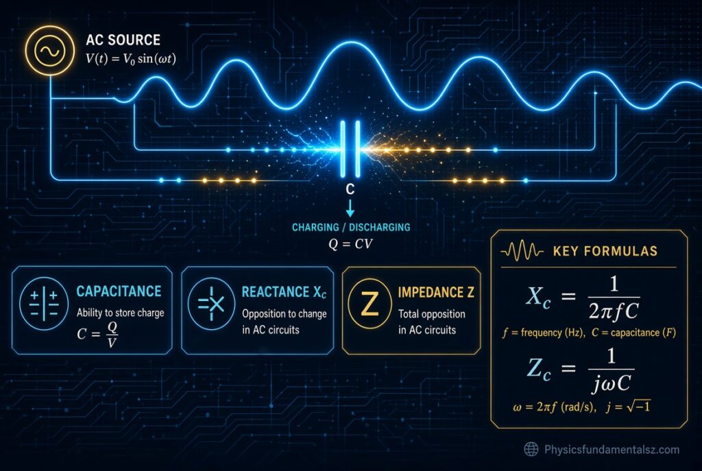
The same combination rules apply in AC circuits, but capacitors also act as frequency-dependent impedances. This is why equivalent capacitance matters for filters and tuning.
Capacitive Reactance
Capacitive reactance is Xc = 1 / (2πfC), where f is frequency in hertz and C is capacitance in farads. A larger capacitance gives a smaller reactance.
At higher frequencies, a capacitor passes AC more easily because Xc falls.
Reactance of Series and Parallel Capacitors
Reactances of series capacitors add, just like resistances. Since Xc is proportional to 1/C, this matches the series formula for capacitance.
Parallel capacitors reduce the total reactance, which matches the fact that total capacitance rises.
Equivalent Capacitance and the RC Time Constant
The time constant of an RC circuit is τ = R × C. When capacitors are combined, use the equivalent capacitance for C.
A larger equivalent capacitance means a slower charge and discharge. A smaller one means a faster response.
Example: Time Constant of a Series Pair
A 10 kΩ resistor charges two 10 μF capacitors in series. The equivalent capacitance is 5 μF.
τ = 10,000 × 0.000005 = 0.05 s, or 50 ms. If the same capacitors were in parallel, Ceq would be 20 μF and τ would be 200 ms.
Practical Considerations When Combining Real Capacitors
Textbook capacitors are perfect. Real ones are not, and a few practical details influence results.
Tolerance
A capacitor labeled 10 μF may measure 8 μF or 12 μF if its tolerance is ±20%. The equivalent capacitance carries the combined error.
When accuracy matters, use film or C0G ceramic types with tighter tolerance.
Equivalent Series Resistance and Inductance
Real capacitors have small internal resistance (ESR) and inductance (ESL). Placing capacitors in parallel lowers the total ESR and ESL, which improves high-frequency filtering.
This is why power supply boards often use several smaller capacitors instead of one large one.
Mixing Different Capacitor Types
Engineers often pair a large electrolytic capacitor with a small ceramic capacitor in parallel. The electrolytic handles low-frequency energy. The ceramic handles fast, high-frequency noise.
The total capacitance is simply the sum, but the combined frequency response is wider than either part alone.
Temperature and Voltage Effects
Some ceramic capacitors lose a large part of their capacitance under DC bias or at temperature extremes. The effective capacitance in the circuit can be much lower than the label.
Check the datasheet curves when exact values matter.
Stray and Parasitic Capacitance
Wires, PCB traces, and component leads add small stray capacitances, usually a few picofarads. These matter in high-frequency and sensitive analog designs.
They appear in parallel with intended capacitors and increase the total.
Real-World Applications of Series and Parallel Capacitors
Combining capacitors is not just a classroom exercise. These networks appear in everyday electronics.
| Application | How Capacitor Combinations Are Used |
|---|---|
| Power supply filtering | Parallel banks smooth ripple and lower ESR |
| Decoupling on circuit boards | Several small parallel capacitors near each chip |
| Radio tuning | Variable and trimmer capacitors combine with fixed ones to set frequency |
| Audio crossovers | Series and parallel combinations reach exact values for filter corners |
| Motor run and start circuits | Parallel capacitors reach required microfarad values |
| Camera flash and energy storage | Series strings handle higher voltage, and parallel banks add energy |
| Supercapacitor modules | Series cells raise voltage, and parallel strings raise capacity |
| Touchscreens | Tiny capacitances combine with finger capacitance to detect touch |
Why Engineers Combine Instead of Buying One Part
A single capacitor may not exist at the exact value, voltage, size, or cost the design needs. Combinations solve these constraints.
They also improve reliability, because failure of one part in a parallel bank has a smaller effect than failure of a single part.
Touchscreens and Sensors
Capacitive touch sensing relies on small changes in total capacitance. A finger adds capacitance in parallel with the sensor, which the controller detects.
The same equivalent capacitance logic applies at a much smaller scale.
Equivalent Capacitance With Dielectrics: Layered and Side-by-Side Layouts
A single parallel-plate capacitor can itself behave like a series or parallel combination. This idea appears often in university physics.
A Dielectric Slab Filling Part of the Gap (Series Behavior)
Suppose a slab of thickness t and dielectric constant κ sits inside a capacitor with plate gap d. The slab and the leftover air gap act like two capacitors in series.
Add the reciprocals: 1/C = (d − t)/(ε₀A) + t/(κε₀A).
Worked Example: Partial Slab
A capacitor has plate area 0.01 m² and gap 2 mm. A 1 mm slab with κ = 4 fills half the gap.
First, ε₀A = 8.854 × 10⁻¹² × 0.01 = 8.854 × 10⁻¹⁴ F·m. The air layer contributes 1 × 10⁻³ / 8.854 × 10⁻¹⁴ ≈ 1.129 × 10¹⁰ F⁻¹. The slab contributes about 2.82 × 10⁹ F⁻¹.
The sum is 1.412 × 10¹⁰ F⁻¹, so C ≈ 70.8 pF. Without the slab, the capacitor would hold about 44.3 pF.
Two Dielectrics Side by Side (Parallel Behavior)
If two dielectrics fill different parts of the plate area, each half acts as its own capacitor, and the two are in parallel.
The total is C = ε₀(κ₁A₁ + κ₂A₂) / d.
Worked Example: Side-by-Side Dielectrics
Use the same plate area of 0.01 m² and gap of 2 mm. Half the area is air (κ = 1) and half is filled with κ = 4.
C = 8.854 × 10⁻¹² × (0.005 × 1 + 0.005 × 4) / 0.002 ≈ 110.7 pF.
Compare this with the partial-slab example. The layout changes the answer even though the same materials are used.
Inserting a Dielectric: Battery Connected vs Disconnected
When a dielectric fills the gap completely, capacitance rises by the factor κ. What happens to charge and voltage depends on the circuit.
| Condition | Capacitance | Voltage | Charge |
|---|---|---|---|
| Battery stays connected | Multiplied by κ | Unchanged | Multiplied by κ |
| Battery disconnected first | Multiplied by κ | Divided by κ | Unchanged |
Variable Capacitors and Trimmers in Tuning Circuits
Radio and RF circuits often combine a fixed capacitor with a variable one. The combination sets the tuning range.
Trimmer in Parallel
A 20 pF fixed capacitor in parallel with a variable capacitor that ranges from 10 pF to 100 pF gives a total from 30 pF to 120 pF.
Parallel combination shifts the whole range upward by the fixed value.
Padder in Series
A variable capacitor from 10 pF to 100 pF in series with a fixed 100 pF capacitor behaves differently. The minimum is about 9.1 pF and the maximum is 50 pF.
Series combination compresses the range, which gives finer control over tuning.
Switching and Charge Redistribution
Many exam problems connect a charged capacitor to an uncharged one through a switch. The key rule is conservation of charge.
Worked Example: Closing a Switch
A 6 μF capacitor is charged to 12 V and then connected in parallel with an uncharged 3 μF capacitor.
Step 1: Initial charge. Q = 6 × 12 = 72 μC.
Step 2: Final capacitance. Ceq = 6 + 3 = 9 μF.
Step 3: Final voltage. V = 72 / 9 = 8 V.
Step 4: Energy. Initially ½ × 6 μF × 144 = 432 μJ. Finally ½ × 9 μF × 64 = 288 μJ. The missing 144 μJ is dissipated during the transfer.
Infinite Ladder Networks of Capacitors
Some advanced problems describe a ladder that repeats forever. The trick is self-similarity: adding one more rung does not change the total.
Setting Up the Equation
Let every capacitor have value C, and let x be the equivalent capacitance of the whole ladder. The first rung has a shunt capacitor C in parallel with a series capacitor C that leads into another identical ladder x.
So x = C + (C × x) / (C + x).
Solving for x
Multiply out and simplify. You get x² − Cx − C² = 0. The positive solution is x = C(1 + √5) / 2, about 1.618 × C.
For C = 10 μF, the infinite ladder has an equivalent capacitance of about 16.18 μF. This is the golden ratio showing up in a circuit.
Tolerance Stack-Up in Series and Parallel
Real capacitors are not exact. Tolerance affects the equivalent capacitance of any combination.
Worked Example
Two 10 μF capacitors with ±20% tolerance are used. Each can range from 8 μF to 12 μF.
In parallel, the total ranges from 16 μF to 24 μF around a nominal 20 μF. In series, the total ranges from 4 μF to 6 μF around a nominal 5 μF.
The relative error stays near ±20% in the worst case, but the absolute spread depends on the connection.
Building Common Values From Identical Capacitors
If you stock only a few values, these combinations cover many targets.
| Target Value | Parts Used | Layout |
|---|---|---|
| 2.5 μF | Four 10 μF | All in series |
| 3.33 μF | Three 10 μF | All in series |
| 5 μF | Two 10 μF | In series |
| 6.67 μF | Three 10 μF | Two in parallel (20 μF), then in series with a third 10 μF |
| 15 μF | Three 10 μF | Two in series (5 μF), then in parallel with a third 10 μF |
| 20 μF | Two 10 μF | In parallel |
| 25 μF | Four 10 μF | Two in parallel, plus a series pair, all in parallel |
| 30 μF | Three 10 μF | All in parallel |
Key Terms in Capacitor Networks
A short glossary makes textbooks and datasheets easier to read.
| Term | Meaning |
|---|---|
| Capacitance | Charge stored per volt, measured in farads |
| Equivalent capacitance | Single value replacing a combination of capacitors |
| Node | A point where two or more components connect |
| Dielectric | Insulating material between the plates |
| Dielectric constant (κ) | Factor by which a dielectric increases capacitance |
| Permittivity of free space (ε₀) | About 8.854 × 10⁻¹² F/m |
| Leakage current | Small current that flows through a real capacitor’s dielectric |
| ESR | Equivalent series resistance of a real capacitor |
| Reactance | Opposition of a capacitor to AC, Xc = 1 / (2πfC) |
| Time constant | τ = R × C, the time scale of charging in an RC circuit |
Equivalent Capacitance Calculator: Spreadsheet and Python Methods
You can check hand calculations quickly with a spreadsheet or a few lines of code. This is useful for long chains and design work.
Spreadsheet Formulas
Place capacitor values in cells A1 to C1, all in the same unit.
| Task | Formula |
|---|---|
| Parallel total | =SUM(A1:C1) |
| Series total (three values) | =1/(1/A1+1/B1+1/C1) |
| Series total (any range) | =1/SUMPRODUCT(1/A1:C1) |
| Two in series | =A1*B1/(A1+B1) |
Python Functions
def series(*caps):
    return 1 / sum(1 / c for c in caps)

def parallel(*caps):
    return sum(caps)

# Example 5: (4 uF in series with 12 uF) in parallel with 5 uF
ceq = parallel(series(4, 12), 5)
print(ceq)  # 8.0
The same functions can be nested to match any mixed network. Each call mirrors one reduction step on paper.
Using an Online Calculator Wisely
Online capacitor calculators are fine for checking answers. Always know the formula yourself, because exams and interviews expect it.
Use the tool to confirm, not to replace understanding.
Capacitance Unit Conversion Reference
Unit conversion is the quietest source of error in capacitor problems. This table covers the usual jumps.
| From | To | Operation |
|---|---|---|
| pF | nF | Divide by 1,000 |
| nF | μF | Divide by 1,000 |
| pF | μF | Divide by 1,000,000 |
| μF | nF | Multiply by 1,000 |
| μF | F | Multiply by 10⁻⁶ |
| mF | μF | Multiply by 1,000 |
Reading Capacitor Codes
Small ceramic capacitors often use three-digit codes. The first two digits are the value, and the third is the multiplier in picofarads.
A code of 104 means 10 followed by four zeros, so 100,000 pF, which equals 100 nF or 0.1 μF. A code of 473 means 47,000 pF, or 47 nF.
Practice Problems on Equivalent Capacitance With Solutions
Try each problem before you read the solution. Working through them builds speed and confidence.
Problem 1: Three Capacitors in Series
Find the equivalent capacitance of 6 μF, 12 μF, and 4 μF in series.
Solution: 1/Ceq = 1/6 + 1/12 + 1/4 = 2/12 + 1/12 + 3/12 = 6/12 = 0.5. So Ceq = 2 μF.
Problem 2: Parallel With Mixed Units
Find the total capacitance of 0.1 μF, 220 nF, and 4.7 μF in parallel.
Solution: 220 nF = 0.22 μF. Ceq = 0.1 + 0.22 + 4.7 = 5.02 μF.
Problem 3: Small Capacitors in Series
Two capacitors of 100 pF and 220 pF are in series. What is the total?
Solution: Ceq = (100 × 220) / (100 + 220) = 22,000 / 320 = 68.75 pF.
Problem 4: Parallel Group in Series
An 8 μF and a 4 μF capacitor are in parallel. That group is in series with a 6 μF capacitor. Find Ceq.
Solution: Parallel group = 12 μF. Ceq = (12 × 6) / (12 + 6) = 72 / 18 = 4 μF.
Problem 5: Charge and Voltage in Series
A 2 μF and a 6 μF capacitor are in series across 24 V. Find the charge and the voltage on each.
Solution: Ceq = 12 / 8 = 1.5 μF. Q = 1.5 × 24 = 36 μC on each capacitor. V₁ = 36 / 2 = 18 V. V₂ = 36 / 6 = 6 V.
Problem 6: Energy in a Parallel Bank
Capacitors of 2 μF, 3 μF, and 5 μF are in parallel across 9 V. Find the total charge and energy.
Solution: Ceq = 10 μF. Q = 10 × 9 = 90 μC. U = ½ × 10 μF × 9² = 405 μJ.
Problem 7: Design a Target Value
How can you make 2.5 μF using only 10 μF capacitors?
Solution: Place four 10 μF capacitors in series. Ceq = 10 / 4 = 2.5 μF.
Problem 8: A Ladder Network
A 10 μF capacitor is in series with a parallel pair. The pair is a 20 μF capacitor and a series chain of 30 μF and 60 μF. Find Ceq.
Solution: The 30 μF and 60 μF chain gives (30 × 60) / 90 = 20 μF. In parallel with 20 μF gives 40 μF. In series with 10 μF gives (10 × 40) / 50 = 8 μF.
Problem 9: Series vs Parallel Energy
Two 10 μF capacitors are connected to a 10 V source, first in series and then in parallel. Compare the energy stored.
Solution: Series Ceq = 5 μF, so U = ½ × 5 μF × 100 = 250 μJ. Parallel Ceq = 20 μF, so U = 1000 μJ. The parallel arrangement stores four times as much energy.
Problem 10: Charge Sharing
A 10 μF capacitor charged to 20 V is connected in parallel with an identical uncharged capacitor. Find the final voltage and the energy change.
Solution: Initial charge = 200 μC. Final Ceq = 20 μF, so V = 200 / 20 = 10 V. Initial energy = ½ × 10 μF × 400 = 2000 μJ. Final energy = ½ × 20 μF × 100 = 1000 μJ. Half of the energy is lost as heat and radiation.
Exam Strategy for Capacitor Combination Problems
A consistent routine keeps you fast and accurate under time pressure.
A Five-Line Checklist
- Write down the terminals and the formulas you plan to use.
- Convert all units to the same unit first.
- Reduce the network one group at a time.
- Check that the answer is smaller than the smallest series capacitor or bigger than the largest parallel one.
- If asked for charge or voltage, work backward through each reduction.
Working Backward to Find Individual Values
After finding Ceq, find the total charge with Q = Ceq × V. Then expand the network step by step. In a series branch, the charge stays the same. In a parallel group, the voltage stays the same.
Repeat until you reach each original capacitor.
Quick Revision Summary
| Topic | Key Point |
|---|---|
| Parallel | Ceq = ΣC, same voltage, charges add |
| Series | 1/Ceq = Σ(1/C), same charge, voltages add |
| Two in series | Ceq = C₁C₂ / (C₁ + C₂) |
| Equal capacitors | Series: C/N. Parallel: N × C |
| Series total | Always smaller than the smallest |
| Parallel total | Always larger than the largest |
| Energy | U = ½ C V² |
| Mixed networks | Reduce step by step from the inside out |
| Units | Convert to one unit before calculating |
| Real parts | Check voltage rating, tolerance, and leakage |
Frequently Asked Questions (FAQs)
How do you find equivalent capacitance in series and parallel?
For parallel capacitors, add all the values: Ceq = C₁ + C₂ + C₃. For series capacitors, add the reciprocals and invert the sum: 1/Ceq = 1/C₁ + 1/C₂ + 1/C₃. Reduce mixed networks one group at a time.
What is the formula for equivalent capacitance in series?
The formula is 1/Ceq = 1/C₁ + 1/C₂ + … + 1/Cₙ. For two capacitors, use Ceq = (C₁ × C₂) / (C₁ + C₂). The result is always smaller than the smallest capacitor.
What is the formula for equivalent capacitance in parallel?
The formula is Ceq = C₁ + C₂ + … + Cₙ. The total is always larger than the largest individual capacitor.
Why does capacitance decrease in series?
Series capacitors act like one capacitor with a larger plate separation. A wider gap holds less charge per volt, so the total capacitance falls.
Why does capacitance increase in parallel?
Parallel capacitors act like one capacitor with a larger plate area. More area lets the plates hold more charge at the same voltage.
Is the equivalent capacitance in series always smaller than each capacitor?
Yes. Because the reciprocals add, the sum of reciprocals is always larger than the reciprocal of any single capacitor. Taking the reciprocal gives a smaller value than every individual capacitance.
What is the difference between series and parallel capacitors?
In series, capacitors share the same charge and their voltages add. In parallel, they share the same voltage and their charges add. Series lowers the total capacitance, and parallel raises it.
Why are capacitor formulas opposite to resistor formulas?
Resistance opposes current, while capacitance measures how much charge is stored per volt. Because of this, the roles of the two connection types swap. Capacitors in parallel add like resistors in series.
How do you find the equivalent capacitance of three capacitors in series?
Add 1/C₁, 1/C₂, and 1/C₃, then take the reciprocal. You can also use Ceq = C₁C₂C₃ / (C₁C₂ + C₂C₃ + C₁C₃). For 1, 5, and 8 μF, the answer is about 0.755 μF.
How do you find the equivalent capacitance of two capacitors in series?
Use the product over sum: Ceq = (C₁ × C₂) / (C₁ + C₂). For 10 μF and 15 μF, the answer is 6 μF.
What is the total capacitance of equal capacitors in series?
Divide one capacitor’s value by the number of capacitors. Four 8 μF capacitors in series give 2 μF.
What is the total capacitance of equal capacitors in parallel?
Multiply one capacitor’s value by the number of capacitors. Four 8 μF capacitors in parallel give 32 μF.
How do you solve mixed series and parallel capacitor circuits?
Identify the simplest series or parallel group, replace it with its equivalent, and redraw. Repeat until only one capacitor remains. Work from the inside of the network outward.
Do capacitors in series have the same charge?
Yes. The same charge Q appears on every capacitor in a series string, because the connecting conductors are electrically isolated and start out neutral.
Do capacitors in parallel have the same voltage?
Yes. All parallel capacitors connect across the same two nodes, so they share the same voltage.
How does voltage divide across capacitors in series?
Voltage divides inversely with capacitance. The smaller capacitor takes the larger share of the total voltage.
How is charge shared among capacitors in parallel?
Charge divides in proportion to capacitance. A larger capacitor stores more charge at the same voltage.
How do you calculate the energy stored in a capacitor combination?
Find the equivalent capacitance and use U = ½ Ceq V². You can also add the energy stored in each capacitor individually, which gives the same result.
Can you connect capacitors with different values in series or parallel?
Yes. The formulas work for any values. In series, check that no capacitor exceeds its voltage rating, since voltage divides unevenly.
Can you mix capacitors with different voltage ratings?
In parallel, the lowest voltage rating limits the group. In series, voltage divides unevenly, so a lower-rated capacitor may be overstressed. Use balancing resistors and matched parts.
What happens if a capacitor is shorted in a network?
A shorted capacitor has zero voltage and stores no charge. You can remove it from the calculation, along with anything the short bypasses.
How do you find equivalent capacitance in a bridge circuit?
If the bridge is balanced, the middle capacitor carries no charge and can be removed. Otherwise use a star-delta transformation or node equations.
How do you convert between pF, nF, and μF?
Divide pF by 1,000 to get nF, and divide nF by 1,000 to get μF. Multiply in the opposite direction to go the other way.
Does equivalent capacitance change in AC circuits?
The capacitance value itself stays the same, but the reactance changes with frequency. Series and parallel rules still apply to the capacitance.
How do you use equivalent capacitance in an RC circuit?
Replace the capacitor network with its equivalent capacitance. Then use τ = R × Ceq to find the time constant.
What is a quick way to check the answer?
Ask whether the answer is smaller than the smallest series capacitor or larger than the largest parallel capacitor. If not, an error has crept in.
Conclusion
Finding equivalent capacitance in series and parallel comes down to two rules. Parallel capacitors add directly, and series capacitors add as reciprocals. Everything else, from mixed networks to bridge circuits, builds on these two ideas.
Always convert units first, redraw the circuit with clear nodes, and reduce one group at a time. Check that series totals fall below the smallest value and parallel totals rise above the largest.
Once you have Ceq, you can find charge, voltage, energy, and time constants with simple relationships. Add real-world awareness of voltage ratings, tolerance, and leakage, and you can design and troubleshoot capacitor networks with confidence.