Wave Interference Explained: How Waves Add, Cancel, and Create Patterns
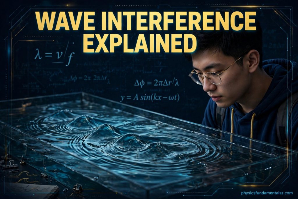
Drop two pebbles into a still pond at the same moment and watch what happens where their ripples meet. In some places the water rises higher than either ripple alone could lift it. In other places the surface goes strangely calm, as if the two ripples had erased each other.
That meeting point is wave interference. It is one of the most beautiful and most useful ideas in all of physics, and once you see it, you start noticing it everywhere: in the rainbow colours of a soap bubble, in the dead spots of a concert hall, in the noise-cancelling headphones on your desk, and in the experiment that first proved light behaves like a wave.
This guide explains wave interference from the ground up. You will learn the superposition principle, the difference between constructive and destructive interference, how to calculate bright and dark fringes, and how to solve the exam-style problems that AP Physics students meet most often.
What Is Wave Interference?
Wave interference happens when two or more waves occupy the same place at the same time. Instead of bouncing off each other or passing through unchanged in some mysterious way, the waves combine. The result is a new pattern of displacement that depends on how the waves line up.
The key point is simple to state and easy to forget under exam pressure: waves add by displacement. At every point, the total displacement of the medium equals the sum of the displacements each wave would produce on its own. If one wave would lift a point by 3 units and another would lift it by 2 units, the point rises by 5 units. If one would lift it by 3 units and the other would push it down by 3 units, the point stays still.
This is very different from how solid objects behave. Two cars cannot occupy the same space, and two billiard balls collide and change direction. Waves, by contrast, pass through each other. After they meet, each wave carries on exactly as before, as if the encounter had never happened. Only during the overlap does the combined pattern appear.
Interference is not a special effect that only happens in laboratories. It happens whenever waves overlap: sound waves from two speakers, water waves from two sources, light waves from two slits, and even the quantum waves that describe electrons. The rules are the same in every case, which is why learning interference once pays off across the whole of physics.
A useful everyday picture is two people pushing a swing. If they push together, in the same direction at the same time, the swing goes higher. That is constructive interference. If one pushes forward while the other pulls back with equal force at the same moment, the swing barely moves. That is destructive interference. Timing, or phase, is everything.
The Superposition Principle
The superposition principle is the rule that makes interference predictable. It states that when two or more waves travel through the same medium, the resulting displacement at any point is the vector sum of the individual displacements.
For waves travelling along a string or across water, displacement is usually up or down, so the sum is just ordinary addition with signs. Up counts as positive and down counts as negative. The principle holds as long as the waves are not so large that the medium itself starts behaving non-linearly, which is true for almost every situation you will meet in school physics.
Superposition explains why interference patterns are stable when the sources are steady. If two sources send out waves continuously with a fixed relationship between them, the pattern of high points, low points, and calm points stays fixed in space. You can photograph it, measure it, and predict it with a formula.
It also explains why the pattern disappears when the sources drift out of step. If the phase relationship between two sources keeps changing randomly, the bright and dark places keep moving, and the eye or the detector sees only an average blur. For a clean, stable interference pattern, the sources must be coherent, meaning they keep a constant phase difference over time.
Coherence is why Young’s famous experiment used a single source split into two, rather than two separate lamps. Two independent lamps flicker out of step billions of times a second, so their interference pattern washes out. One source, divided into two paths, stays in step with itself, and the pattern holds still long enough to see.
Students sometimes ask whether superposition means energy is created or destroyed. It does not. In constructive interference, the extra energy at a bright spot is balanced by missing energy at a dark spot. Energy is redistributed, not created. The total energy, averaged over the whole pattern, equals the sum of the energies the waves would carry separately.
Constructive Interference: When Waves Add Up
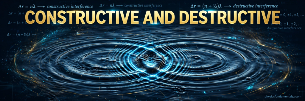
Constructive interference occurs when two waves arrive in phase, crest matching crest and trough matching trough. Their displacements add, producing a larger amplitude than either wave alone.
For two identical waves of amplitude A, perfect constructive interference gives an amplitude of 2A. Because wave intensity is proportional to amplitude squared, the intensity at that point is four times the intensity of one wave alone, not merely double. That squaring catches many students out, so it is worth remembering: double the amplitude means four times the intensity.
Constructive interference needs a path difference of a whole number of wavelengths. If one wave has travelled exactly one, two, or three wavelengths further than the other, the two waves still arrive in step, because a whole wavelength of extra travel just delays the wave by one full cycle. In symbols, constructive interference happens when the path difference equals m times lambda, where m is an integer (0, 1, 2, 3, and so on) and lambda is the wavelength.
In a ripple tank, constructive interference shows up as lines of tall, choppy water radiating from between the two sources. In a double-slit experiment, it shows up as bright fringes on the screen. In sound, it shows up as loud spots in the room. The medium changes, but the geometry is the same.
A practical example is a concert speaker system. Sound engineers deliberately arrange speakers so that the waves add constructively in the audience area and cancel in directions where sound would disturb neighbours. The same principle, run in reverse, creates quiet zones. Interference is not just a classroom curiosity; it is an engineering tool.
Destructive Interference: When Waves Cancel Out
Destructive interference is the opposite case. Two waves arrive exactly out of phase, crest matching trough. Their displacements cancel, and the medium at that point barely moves at all.
For two identical waves, perfect destructive interference gives zero amplitude and zero intensity at that point. The waves have not vanished, of course. Each wave is still travelling through the medium. They simply add to zero at that particular place, at that particular time, because they are exactly opposed.
Destructive interference needs a path difference of half a wavelength, or an odd number of half wavelengths: lambda over 2, 3 lambda over 2, 5 lambda over 2, and so on. An extra half wavelength flips a crest into a trough, so the two waves arrive opposed.
In a ripple tank, destructive interference produces calm lines between the choppy lines, where the water surface stays almost flat even though waves are passing through it. In a double-slit experiment, it produces dark fringes. In sound, it produces quiet spots, sometimes called dead spots, where a tone that is loud a metre away becomes almost inaudible.
Noise-cancelling headphones are the most famous everyday application. A microphone listens to the incoming noise, the headphone electronics generate a copy of that sound wave shifted by half a cycle, and the two waves cancel in your ear. The cancellation is never perfect across all frequencies, but for steady low-frequency hums such as aeroplane engines, it is remarkably effective.
It is important to be precise about what “cancel” means. Destructive interference does not destroy the waves or their energy. The energy that is missing from the quiet spot appears in the loud spots nearby. If you could measure the total sound energy in the whole room, it would be unchanged. Interference moves energy around; it never makes it disappear.
Phase Difference and Path Difference
Two quantities control interference, and confusing them is the most common source of errors. Path difference is a distance: how much further one wave has travelled than the other to reach a point. Phase difference is an angle, measured in radians or degrees, that describes how far through its cycle one wave is compared with the other.
The two are linked by the wavelength. A path difference of one full wavelength corresponds to a phase difference of 2 pi radians, or 360 degrees. A path difference of half a wavelength corresponds to a phase difference of pi radians, or 180 degrees. In general, phase difference equals 2 pi times path difference divided by wavelength.
Sources can also start out of phase. If one source begins its vibration half a cycle after the other, that built-in phase difference must be added to the phase difference caused by the path. Most textbook problems use sources that start in phase, so the path difference alone decides the result, but always check the question. A problem that says the sources are “in antiphase” or “pi out of phase” is telling you to flip every constructive result into a destructive one.
Phase is also the language of thin films and reflections, where a wave can gain an extra half-cycle phase shift simply by reflecting off a denser medium. That single detail explains soap bubble colours, anti-reflective coatings, and oil slick rainbows, and it is covered in detail later in this article.
A good habit is to convert every interference question into the same two steps. First, find the path difference to the point of interest. Second, compare that path difference with the wavelength. Whole wavelengths mean constructive, half wavelengths mean destructive, and anything in between means partial interference with an amplitude somewhere between zero and the maximum.
Young’s Double Slit Experiment
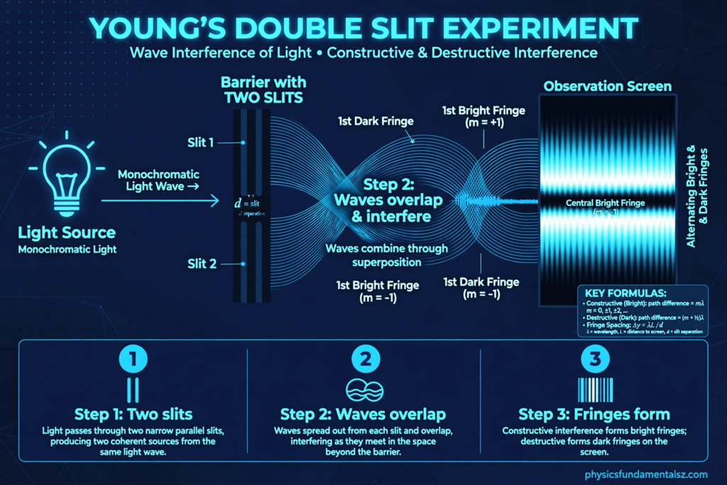
In 1801, Thomas Young shone light through two narrow, closely spaced slits and observed a pattern of bright and dark bands on a screen behind them. The result was decisive. Particles travelling in straight lines could not produce such a pattern, but waves interfering with each other could. Young’s experiment is still the classic demonstration that light behaves as a wave (Britannica explains interference of waves), and it remains a favourite exam topic for exactly that reason.
The setup is simple. Light from a single source passes through a single slit, then through two slits a small distance apart. The two slits act as coherent sources, in step with each other. Their waves spread out, overlap, and interfere on a distant screen, producing a series of equally spaced bright fringes separated by dark fringes.
The geometry gives a beautifully simple formula. If d is the slit separation, lambda is the wavelength, L is the distance from slits to screen, and y is the distance from the central bright fringe to a bright fringe of order m, then for small angles, y equals m times lambda times L divided by d. The fringe spacing, the distance between neighbouring bright fringes, is lambda times L divided by d.
That formula tells you everything about how the pattern changes. Move the screen further away and the fringes spread out. Use light of a longer wavelength, such as red instead of blue, and the fringes spread out. Move the slits closer together and the fringes spread out. Move the slits further apart and the fringes squeeze together. Every one of those predictions can be tested in a school laboratory, and examiners love asking about them qualitatively as well as numerically.
The central fringe, at m equals zero, is bright, because light from both slits travels the same distance to the centre of the screen and arrives in phase. The first dark fringes sit on either side, where the path difference is half a wavelength. The pattern is symmetric, and the bright fringes gradually fade towards the edges in a real experiment because each slit also diffracts light, but the core spacing rule stays the same.
Young’s experiment also shows why white light produces coloured fringes. White light contains many wavelengths, and each wavelength produces its own fringe pattern with its own spacing. At the centre they all overlap and give white, but further out the patterns separate, so the fringes become coloured, with blue on the inside and red on the outside, because red light spreads further.
If you want a deeper grounding in the wave ideas behind this experiment, it helps to revisit how waves themselves are described. Our guide to transverse and longitudinal waves explains the two wave types, and our explanation of the Doppler effect shows another case where wave geometry produces a striking observable effect.
Worked Example: Double Slit Fringe Spacing
Worked problems make the formula stick, so here is a standard one, solved step by step.
A double slit experiment uses green light of wavelength 550 nanometres. The slit separation is 0.20 millimetres and the screen is 2.0 metres from the slits. Find the fringe spacing.
First, convert everything to metres. The wavelength is 550 times 10 to the power minus 9 metres. The slit separation is 0.20 times 10 to the power minus 3 metres, which is 2.0 times 10 to the power minus 4 metres. The screen distance is 2.0 metres.
Fringe spacing equals lambda times L divided by d. Substituting gives (550 times 10 to the power minus 9 times 2.0) divided by (2.0 times 10 to the power minus 4). The 2.0 cancels, leaving 550 times 10 to the power minus 9 divided by 10 to the power minus 4, which is 550 times 10 to the power minus 5 metres, or 5.5 millimetres.
That is a sensible, measurable spacing, and it shows why the experiment works so well in a laboratory. If you swapped the green light for red light of wavelength 650 nanometres, the spacing would grow to about 6.5 millimetres, because fringe spacing is directly proportional to wavelength. If you doubled the slit separation, the spacing would halve. Proportional reasoning like this answers many multiple-choice questions without any calculator work at all.
A second worked example tests path difference directly. Two coherent sources, A and B, are 6.0 centimetres apart. A point P is 5.0 centimetres from A and 6.5 centimetres from B. The waves have a wavelength of 1.0 centimetre. What kind of interference occurs at P?
The path difference is the difference of the two distances: 6.5 minus 5.0 equals 1.5 centimetres. Dividing by the wavelength, 1.5 centimetres is 1.5 wavelengths, which is an odd number of half wavelengths (3 half wavelengths). The waves therefore arrive out of phase, and destructive interference occurs at P. If the distance from B had been 7.0 centimetres instead, the path difference would be 2.0 wavelengths, a whole number, and the interference would be constructive.
Notice the method: find the path difference, divide by the wavelength, and ask whether the result is a whole number or a half-integer. That single check solves a large family of interference problems, from ripple tanks to sound to light.
Thin Film Interference: Soap Bubbles and Oil Slicks
Thin film interference explains some of the prettiest colours in nature. A soap bubble is a thin film of soapy water with air on both sides. Light reflects off the outer surface and off the inner surface. Those two reflected waves then interfere, and the result depends on the film thickness and the wavelength.
The subtlety is the phase change on reflection. When light reflects off a boundary with a denser medium, it gains a phase shift of half a cycle, pi radians. When it reflects off a boundary with a less dense medium, it gains no phase shift. For a soap film in air, the outer reflection (air to soap, denser) gains half a cycle, while the inner reflection (soap to air, less dense) gains none. That built-in half-cycle difference flips the usual rules: for a very thin film, the two reflected waves cancel, which is why the top of an old, thin bubble looks dark just before it pops.
As the film thickness varies, different wavelengths satisfy the constructive condition at different places, so different colours appear at different thicknesses. That is why a bubble shows swirling bands of colour rather than a single flat tint. The same physics colours an oil slick on a wet road and a layer of petrol on water.
Engineers use the same idea in reverse. An anti-reflective coating on a camera lens or on spectacles is a thin film whose thickness is chosen so that reflected light interferes destructively for the middle of the visible spectrum, a case HyperPhysics describes for thin film interference. Less light is reflected, more light passes through, and glare drops dramatically. A single coating cannot cancel every wavelength perfectly, which is why coated lenses often show a faint purple or green tint: the leftover reflected light is mostly at the ends of the spectrum.
The key exam point is this: always ask whether a reflection adds a phase shift before applying the path difference rule. Forgetting the half-cycle shift at a denser boundary is the single most common error in thin film questions, and it reverses every answer.
Beats: Interference in Time
Interference does not only happen in space. It also happens in time, and the result is called beats. When two sound waves of slightly different frequencies overlap, they drift in and out of phase. When they are in phase, the sound is loud. When they are out of phase, the sound is quiet. The listener hears a regular pulsing, or beating, at a frequency equal to the difference between the two frequencies.
If one tuning fork vibrates at 440 hertz and another at 444 hertz, the beat frequency is 4 hertz, so the listener hears four loud-soft pulses per second. Musicians use beats to tune instruments (Khan Academy covers wave interference and beats): they play a reference note and the note being tuned together, and adjust until the beating slows to zero, meaning the two frequencies match exactly.
Beats are interference with a twist. Instead of a fixed pattern in space, the pattern moves through time at a single point, your ear. The mathematics is the same superposition, but the variable is time rather than position. The beat frequency formula, the absolute difference of the two frequencies, is simple and very testable.
The idea extends beyond sound. In radio and electronics, mixing two signals of slightly different frequencies produces a beat signal, and that principle sits behind heterodyne receivers and some kinds of radar. Whenever two nearly equal frequencies meet, beats are waiting to happen.
Standing Waves: Interference That Stays Put
When two identical waves travel in opposite directions through the same medium, their interference produces a standing wave. The pattern does not travel. Instead, fixed points called nodes stay still, while points called antinodes vibrate with maximum amplitude.
A guitar string is the classic example. Pluck it, and waves travel to both ends, reflect, and interfere with the waves coming the other way. Only certain wavelengths fit neatly onto the string, with nodes at both fixed ends. Those allowed wavelengths are the harmonics of the string, and they are why a guitar produces musical notes rather than noise.
Standing waves also appear in pipes, microwave ovens, and even in the quantum description of electrons in atoms. In every case, the same rule applies: the wave must fit the space, with the boundary conditions deciding where nodes and antinodes fall. A string fixed at both ends has nodes at both ends. A pipe open at one end and closed at the other has a node at the closed end and an antinode at the open end.
For students, the link between standing waves and interference is worth making explicit. A standing wave is not a different phenomenon. It is interference, with the two waves travelling in opposite directions instead of side by side. The nodes are places of permanent destructive interference, and the antinodes are places of permanent constructive interference.
Our guide to simple harmonic motion covers the vibrations that underlie standing waves, and the sound waves and frequency guide connects frequency, wavelength, and pitch in the context of musical instruments.
Interference of Sound: Loud Spots, Dead Spots, and Concert Halls
Sound interference is easy to demonstrate and easy to experience. Set up two speakers playing the same pure tone, walk across the room, and you will pass through loud spots and quiet spots. The tone does not change, and the speakers do not move. Only your position changes, and with it the path difference from the two speakers to your ears.
Architects and acousticians fight this effect constantly. A concert hall with flat, parallel walls can develop strong interference patterns that make some seats boomy and others thin. The remedies are curved surfaces, diffusers that scatter sound in many directions, and absorbent materials that reduce reflections. Modern halls are shaped by interference physics as much as by architecture.
The same effect causes trouble in smaller rooms. A home cinema with two speakers and bare walls can have a “sweet spot” where the sound is excellent and dead spots a step away where bass disappears. Moving a speaker by a few centimetres changes the path differences and can shift the pattern noticeably, which is why speaker placement guides obsess over small distances.
Interference also explains why a single speaker sounds different outdoors and indoors. Outdoors, there is mainly the direct wave. Indoors, reflected waves from walls, floor, and ceiling arrive slightly later and interfere with the direct wave, boosting some frequencies and cutting others. The room itself becomes part of the instrument.
Diffraction and Interference: Close Cousins, Not Twins
Students often confuse diffraction and interference, because they appear together in most experiments. The distinction is worth getting right.
Diffraction is the spreading of a wave when it passes through a gap or around an obstacle. A single slit produces a diffraction pattern on its own, with a broad central maximum and fainter side maxima. Interference is the combination of waves from two or more sources. A double slit produces an interference pattern, but each slit also diffracts, so the real pattern is interference fringes inside a diffraction envelope.
A helpful rule: diffraction is what one source does when it is constrained; interference is what two or more sources do when they overlap. In the double slit, you get both at once. In a diffraction grating, with hundreds or thousands of slits, interference becomes extremely sharp, which is why gratings are used to measure wavelengths precisely and to split light in spectrometers.
Diffraction also sets a limit on how sharp an image can be. A telescope or a camera cannot resolve details smaller than the diffraction pattern of its aperture allows. That is why larger telescopes see finer detail: a bigger aperture makes a narrower diffraction pattern. Interference sharpens measurement; diffraction limits resolution. Physics gives with one hand and takes with the other.
Common Mistakes in Wave Interference
The first common mistake is mixing up path difference and phase difference. Path difference is measured in metres, phase difference in radians. A path difference of half a wavelength is a phase difference of pi radians. Writing “phase difference equals lambda over 2” loses marks, because the units are wrong even though the idea is right.
The second mistake is forgetting coherence. Two waves from independent sources do not produce a stable pattern, no matter how carefully you arrange them. Exam questions that mention “coherent sources” are giving you a necessary condition, not decoration. If the sources were not coherent, there would be no steady fringes to measure.
The third mistake is applying the bright-fringe formula to dark fringes. Bright fringes sit at path differences of m lambda. Dark fringes sit at path differences of (m plus one half) lambda. If a question asks for the first dark fringe, m equals zero in the dark formula gives half a wavelength, not zero. Counting from the centre carefully avoids this trap.
The fourth mistake is the reflection phase shift in thin films, already discussed above. Always check both reflecting surfaces and ask whether each one is a denser boundary. One shift flips the pattern; two shifts cancel each other out.
The fifth mistake is assuming destructive interference destroys energy. It redistributes energy. If a question asks about energy conservation, the answer is that bright fringes gain exactly what dark fringes lose, averaged over the pattern.
Real-World Applications
Interference is not confined to textbooks. Noise-cancelling headphones use destructive interference to cut engine hum. Anti-reflective coatings use thin film interference to cut glare. Diffraction gratings use multi-slit interference to analyse the light from stars and identify the elements in their atmospheres.
In medicine, ultrasound imaging relies on the interference of reflected sound waves to build pictures of the inside of the body. In engineering, interferometers measure distances with extraordinary precision by counting interference fringes as a mirror moves. The LIGO gravitational wave detectors are giant interferometers, with arms four kilometres long, that detect changes in length smaller than a proton’s width by watching interference fringes shift.
Even the colours of butterfly wings and peacock feathers are interference colours, produced by microscopic structures rather than pigments. The structures are thin films and gratings built by nature, and they produce colours that never fade because there is no dye to bleach. Nature discovered thin film interference long before physicists named it.
For a related pressure-and-fluids topic that also relies on waves and forces in a medium, see our guide to Archimedes’ principle, and for the forces that govern how fluids move, see Bernoulli’s principle.
Frequently Asked Questions
What is wave interference in simple terms?
Wave interference is what happens when two or more waves meet in the same place. Their displacements add together. If they line up crest to crest, they make a bigger wave. If they line up crest to trough, they cancel each other out. The waves then carry on unchanged after passing through each other.
What is the difference between constructive and destructive interference?
Constructive interference happens when waves arrive in phase, with a path difference of a whole number of wavelengths, and their amplitudes add. Destructive interference happens when waves arrive out of phase, with a path difference of an odd number of half wavelengths, and their amplitudes cancel. Constructive gives bright fringes or loud spots; destructive gives dark fringes or quiet spots.
What are the conditions for interference?
Two conditions matter most. The sources must be coherent, keeping a constant phase difference, and they must have the same frequency (and ideally similar amplitude) so the pattern stays stable. Without coherence, the pattern shifts too fast to see. Without equal frequency, the phase relationship drifts and the pattern washes out.
Why does Young’s double slit experiment prove light is a wave?
Particles travelling in straight lines through two slits would pile up in two bright bands, one behind each slit. Young observed many evenly spaced bright and dark bands, which only wave interference can produce. The dark bands are places where light plus light gives darkness, something no particle picture can explain.
Can two waves cancel completely?
Yes, at a particular point, if they have equal amplitude and arrive exactly out of phase. The displacement there is zero. The waves themselves do not disappear, and the energy is not destroyed; it appears in the bright regions nearby. Complete cancellation at every point at once would violate energy conservation and does not happen.
What is the difference between interference and diffraction?
Diffraction is the spreading of a single wave through a gap or around an edge. Interference is the combination of two or more waves. A double-slit pattern shows both: interference fringes from the two slits, shaped by the diffraction pattern of each individual slit.
Conclusion
Wave interference is a simple rule with spectacular consequences. Waves add by displacement. Whole wavelengths of path difference give constructive interference, half wavelengths give destructive interference, and everything else falls in between. From that one rule come fringe patterns, soap bubble colours, beats, standing waves, noise cancellation, and gravitational wave detectors.
The best way to master interference is to practise the two-step method on every problem: find the path difference, then compare it with the wavelength. Add the reflection phase shift when thin films are involved, check for coherence, and keep path difference and phase difference in their proper units. Do that, and the fringes, the formulas, and the exam questions all fall into place.
Next time you see a soap bubble, listen to a pair of speakers, or put on noise-cancelling headphones, remember what is happening. Waves are meeting, adding, and cancelling, and the pattern you see or hear is interference doing its quiet, everyday work.
Sources for further reading: OpenStax University Physics: Interference, HyperPhysics: Interference, Khan Academy: Wave interference, Britannica: Interference of waves.