Polarisation of Light: Malus’s Law I = I₀cos²θ & Applications
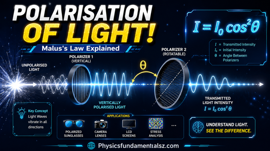
Polarisation of light is the property that describes the direction in which a light wave vibrates, and it is one of the most useful concepts in all of optics, powering everything from polarised sunglasses to LCD screens to advanced microscopy.
Table of Contents
What Is Polarisation of Light?
Light is an electromagnetic transverse wave, which means its electric and magnetic fields oscillate perpendicular to the direction the wave travels. Polarisation of light refers to the orientation of that oscillating electric field.
In most natural light sources, such as sunlight, incandescent bulbs, and LED lighting, the electric field vibrates in many different directions at once, all perpendicular to the direction of travel. This is called unpolarised light. When the electric field is restricted so that it vibrates in only one specific direction, or follows a predictable rotating pattern, the light is said to be polarised.
Because polarisation depends entirely on the transverse nature of the wave, it is a phenomenon unique to transverse waves. Longitudinal waves, such as sound, cannot be polarised because their oscillations already occur along the direction of travel rather than perpendicular to it.
Why Only Transverse Waves Can Be Polarised
To understand polarisation properly, it helps to compare transverse and longitudinal waves directly. In a transverse wave, the medium (or field) oscillates at right angles to the direction of propagation, which leaves an entire plane of possible oscillation directions available. Polarisation is simply the selection or restriction of one of those directions.
In a longitudinal wave, the oscillation happens along the same line as the direction of travel, so there is no additional plane of directions to restrict. This is a key reason polarisation is often used as experimental proof that light behaves as a transverse wave rather than a longitudinal one, a distinction covered in more depth in this guide on how wave speed, frequency and wavelength relate across different wave types.
Types of Polarised Light
Polarisation of light is generally classified into three main types, based on how the electric field vector behaves as the wave propagates.
Linear Polarisation
In linear polarisation, the electric field oscillates back and forth along a single fixed direction. If you could freeze a linearly polarised wave in time and look along its path, the tip of the electric field vector would trace out a straight line. Linear polarisation is the simplest and most common type produced by polarising filters.
Circular Polarisation
In circular polarisation, two linear waves of equal amplitude oscillate perpendicular to each other with a 90 degree phase difference. Rather than staying fixed in one direction, the resulting electric field vector rotates steadily as the wave travels, tracing out a circle when viewed head-on. Depending on the direction of rotation, circularly polarised light is described as left-handed or right-handed.
Elliptical Polarisation
Elliptical polarisation is the general case that includes both linear and circular polarisation as special cases. It occurs when two perpendicular linear components have unequal amplitudes, an arbitrary phase difference, or both. The electric field vector traces out an ellipse rather than a perfect circle or a straight line.
How Polarising Filters Work
A polarising filter, often called a polariser, is made from long-chain molecules aligned in a single direction. These molecules absorb electric field components that oscillate parallel to the molecular chains while allowing components perpendicular to the chains to pass through relatively unaffected.
When unpolarised light passes through a single polariser, only the component of the electric field aligned with the filter’s transmission axis survives, so the emerging light becomes linearly polarised. Since unpolarised light contains all orientations equally, roughly half the original intensity is transmitted through an ideal polariser, and the other half is absorbed or blocked.
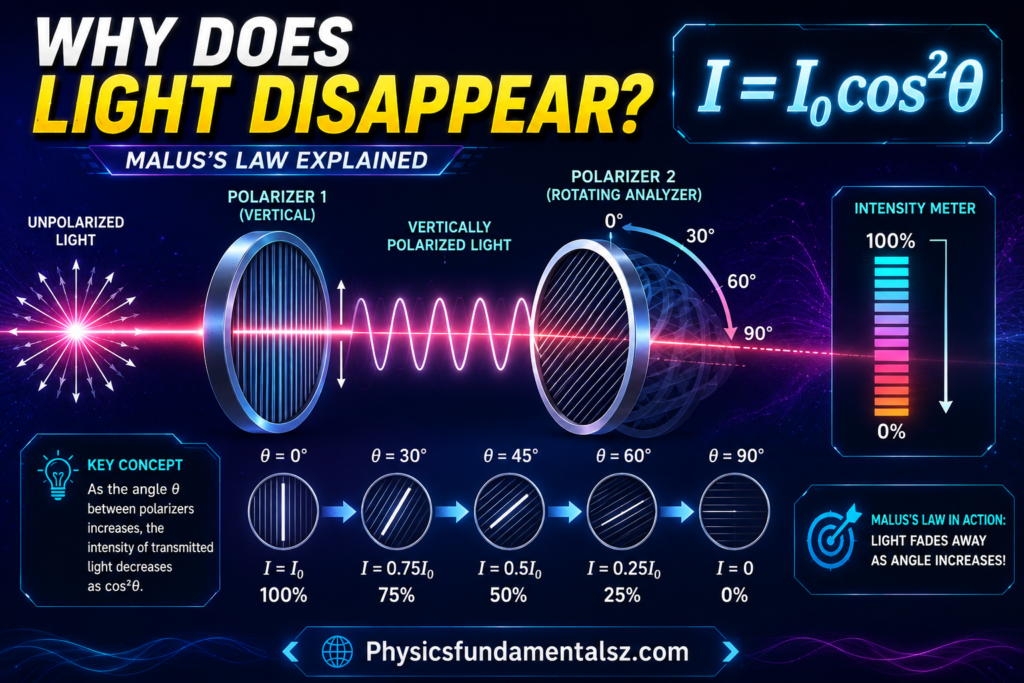
Once light has been linearly polarised by a first filter, passing it through a second filter reveals a much more precise relationship between filter orientation and transmitted intensity. This relationship is described by Malus’s Law.
Malus’s Law: I = I₀cos²θ Explained
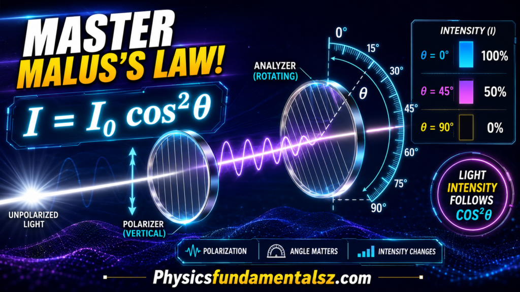
Malus’s Law is the fundamental equation describing how the intensity of polarised light changes as it passes through a second polarising filter, called the analyser. Named after French physicist Etienne Louis Malus, who discovered the relationship in 1809, the law is written as:
I = I₀cos²θ
where I is the intensity of light transmitted through the analyser, I₀ is the intensity of the light entering the analyser (already linearly polarised), and θ is the angle between the polarisation direction of the incoming light and the transmission axis of the analyser.
Understanding the Malus’s Law Formula
The cos²θ relationship comes directly from resolving the electric field vector into components. Only the component of the electric field aligned with the analyser’s transmission axis is transmitted, and since intensity is proportional to the square of the electric field amplitude, the transmitted intensity scales with the square of the cosine of the angle between the two axes.
When θ equals 0 degrees, the two polarising axes are perfectly aligned, cos²θ equals 1, and all of the incoming polarised light passes through, so I equals I₀. When θ equals 90 degrees, the axes are perpendicular, cos²θ equals 0, and no light is transmitted at all, a configuration known as crossed polarisers. At intermediate angles, the transmitted intensity varies smoothly between these two extremes.
Worked Example of Malus’s Law
Suppose linearly polarised light with an intensity of 100 watts per square metre passes through an analyser oriented at 30 degrees relative to the light’s polarisation direction. Applying the formula:
I = 100 × cos²(30°) = 100 × (0.866)² = 100 × 0.75 = 75 W/m²
This means 75 percent of the incoming intensity is transmitted through the analyser at a 30 degree offset, illustrating how quickly intensity falls off as the angle between polarisers increases.
Polarisation by Reflection and Brewster’s Angle
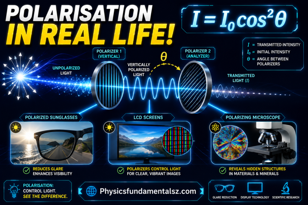
Polarisation of light does not only happen through filters. It also occurs naturally when light reflects off a non-metallic surface, such as water, glass, or a road surface. Reflected light becomes partially polarised in the direction parallel to the reflecting surface, which is exactly why polarised sunglasses, typically oriented to block horizontally polarised light, are so effective at reducing glare from puddles, wet roads, and open water.
At one specific angle of incidence, called Brewster’s angle, the reflected light becomes completely polarised. At this angle, the reflected ray and the refracted ray are perpendicular to each other, and only light polarised parallel to the reflecting surface is reflected, while the perpendicular component is entirely transmitted. This angle depends on the refractive indices of the two materials involved, connecting polarisation directly to the broader physics of reflection and refraction.
Polarisation and the Electromagnetic Spectrum
Polarisation is not limited to visible light. Since polarisation is a property of any transverse electromagnetic wave, it applies across the entire electromagnetic spectrum, including radio waves, microwaves, infrared, ultraviolet, X-rays, and gamma rays. This is why radio and television antennas must be oriented correctly relative to the polarisation of the broadcast signal, and why satellite communication systems rely heavily on carefully controlled polarisation to avoid signal interference.
Applications of Polarisation of Light
Polarisation of light shows up in a wide range of practical technologies, far beyond the physics classroom.
Polarised sunglasses use a vertically oriented polarising filter to block the horizontally polarised glare that reflects off flat surfaces like water and pavement, improving visual comfort and clarity.
LCD screens rely on precisely controlled polarisation. Liquid crystal displays sandwich a layer of liquid crystals between two polarising filters, and applying a voltage twists the liquid crystal molecules to control how much light passes from one polariser to the other, generating an image pixel by pixel.
Photography benefits from polarising filters attached to camera lenses, which can reduce reflections from glass and water, deepen the appearance of blue skies, and increase color saturation in outdoor shots.
3D cinema systems frequently use circular or linear polarisation to project two slightly different images simultaneously, with polarised glasses ensuring each eye only receives the image intended for it, creating the illusion of depth.
Stress analysis in engineering uses a technique called photoelasticity, where transparent materials placed between crossed polarisers reveal internal stress patterns as colorful interference fringes, helping engineers identify weak points in components before they are manufactured.
Optical communication and remote sensing use polarisation to encode additional information into light signals or to distinguish between different types of surfaces and materials based on how they polarise reflected sunlight, a technique widely used in satellite imaging and atmospheric science.
Polarisation and Wave Interference
Polarisation also interacts closely with wave interference phenomena. In experiments involving multiple coherent light sources, such as the classic setup in Young’s double-slit experiment, the polarisation state of the light sources affects whether clear interference fringes can form. Two beams must share a compatible polarisation state to interfere constructively and destructively in a predictable pattern, which is why polarisation control is essential in many precision optics experiments.
Polarisation in Nature
Polarisation of light is not just a laboratory or engineering phenomenon. It occurs naturally and is used by living organisms in remarkable ways. Sunlight scattering through the atmosphere becomes partially polarised, forming predictable patterns across the sky that change with the sun’s position. Many insects, including bees and ants, can detect this atmospheric polarisation pattern and use it as a natural compass to navigate, even on overcast days when the sun itself is not visible.
Some marine animals, such as mantis shrimp and certain species of cuttlefish, can detect and even produce polarised light patterns, using them for camouflage disruption and covert communication that predators cannot perceive. The human eye is far less sensitive to polarisation, though a faint effect called Haidinger’s brush, a subtle yellowish bowtie-shaped pattern, can sometimes be seen when staring at a strongly polarised light source such as a blue sky, offering a rare glimpse of a sense most other animals rely on far more heavily.
Multiple Polarisers and the Three-Polariser Paradox
An especially interesting demonstration of Malus’s Law involves three polarising filters placed in sequence. If two polarisers are crossed at 90 degrees, no light passes through, since cos²(90°) equals zero. However, if a third polariser is inserted between the two crossed polarisers at an intermediate angle, such as 45 degrees, some light unexpectedly reappears on the other side.
This happens because each polariser only interacts with the light immediately incident on it. The first polariser produces linearly polarised light. The middle polariser, set at 45 degrees to both outer polarisers, transmits a portion of that light according to Malus’s Law and, crucially, re-polarises it along its own axis. The final polariser then transmits a portion of this newly polarised light relative to its own axis. Multiplying the two intensity reduction factors together, using cos²(45°) twice, shows that 25 percent of the original polarised intensity can pass through the full three-filter system, even though no light at all could pass through just the first and last filters alone. This result often surprises students, since it seems to violate intuition, but it follows directly and exactly from applying Malus’s Law at each interface in turn.
Polarisation by Scattering
Beyond reflection and filtering, polarisation of light can also result from scattering, which is the process responsible for the polarisation patterns seen across the daytime sky. When sunlight strikes gas molecules in the atmosphere, the oscillating electric field of the incoming wave causes electrons in the molecule to vibrate and re-radiate light in a new direction. This scattered light is most strongly polarised at a 90 degree angle from the original direction of the sunlight, which is why the region of sky roughly a quarter turn away from the sun appears most strongly polarised, while the sky near the sun itself shows very little polarisation.
This scattering-based polarisation has practical uses as well. Photographers use polarising filters to darken blue skies most effectively when shooting at roughly 90 degrees to the sun, since this is where atmospheric polarisation, and therefore the filter’s effect, is strongest.
Measuring Polarisation: The Degree of Polarisation
In many real situations, light is neither perfectly polarised nor completely unpolarised, but instead partially polarised, containing a mixture of a polarised component and a random unpolarised component. This mixture is quantified using the degree of polarisation, defined as the fraction of the total light intensity that is polarised.
A degree of polarisation of 1, or 100 percent, describes fully polarised light, while a degree of polarisation of 0 describes completely unpolarised light. Most natural light sources, and most reflected light encountered in everyday situations, fall somewhere between these two extremes, which is precisely why polarised sunglasses reduce glare noticeably without eliminating all light entirely.
Frequently Asked Questions (FAQs)
What is the difference between polarised and unpolarised light?
Unpolarised light contains electric field oscillations in every direction perpendicular to its travel path, while polarised light has its electric field restricted to a single direction, a rotating circular pattern, or an elliptical pattern.
What does Malus’s Law calculate?
Malus’s Law, I = I₀cos²θ, calculates the intensity of linearly polarised light after it passes through a polarising analyser, based on the angle between the light’s polarisation direction and the analyser’s transmission axis.
Why do polarised sunglasses reduce glare?
Reflected light off flat surfaces like water and roads becomes mostly horizontally polarised. Polarised sunglasses use a vertical polarising filter that blocks this horizontal component, significantly reducing glare while still allowing most useful light through.
Can sound waves be polarised?
No, sound waves are longitudinal waves, and polarisation only applies to transverse waves where oscillation occurs perpendicular to the direction of propagation. Since sound oscillates along its direction of travel, there is no additional direction to restrict.
What is Brewster’s angle?
Brewster’s angle is the specific angle of incidence at which reflected light becomes completely polarised, occurring when the reflected and refracted rays are perpendicular to each other.
Conclusion
Polarisation of light connects some of the most elegant ideas in optics, from the transverse nature of electromagnetic waves to the precise mathematics of Malus’s Law and its formula I = I₀cos²θ.
Understanding linear, circular, and elliptical polarisation, how polarising filters and Brewster’s angle work, and how these principles power technologies like LCD screens, polarised sunglasses, and 3D cinema gives you a complete practical and theoretical grasp of one of physics’ most widely applied wave phenomena.