Difference Between AC and DC Current Explained
Quick answer: Direct current (DC) flows in one direction only, at a steady value. Alternating current (AC) reverses direction repeatedly, following a sine wave. Homes and power grids use AC because it is easy to transform to high voltages for efficient transmission. Batteries and electronics use DC because circuits and devices need a steady, one-way supply.
Almost every electrical device you own depends on this distinction. Your phone charger converts AC from the wall socket into DC for the battery. Your laptop, torch, and car all run on DC. The power station miles away, and the grid that carries its energy to your street, run on AC.
Students often learn AC and DC as two labels to memorise. That approach misses the physics. The two current types differ in direction, waveform, frequency, generation, transmission, and safety. Each difference follows from a simple idea about how charge moves.
This guide explains both current types from the ground up. You will learn definitions, waveforms, key quantities, generation methods, worked calculations, and real uses. You will also see the advantages and limits of each type, plus the exam traps that appear most often.
What Is Electric Current?
Electric current is the rate of flow of electric charge. In a metal wire, the moving charges are electrons. In a battery electrolyte or a plasma, ions carry the charge. The direction of conventional current is defined as the direction positive charge would flow, which is opposite to electron flow in metals.
Current is measured in amperes (A). One ampere means one coulomb of charge passing a point each second. The symbol for current is I. Current flows only when a complete circuit exists and a voltage, or potential difference, drives the charge around it. Khan Academy’s physics course introduces current, voltage, and resistance together, and the OpenStax University Physics textbook covers charge flow and drift velocity in depth. Our guide to electric current explains charge flow, drift velocity, and current in more detail.
Voltage is the energy transferred per unit charge. Current tells you how much charge flows per second. Power tells you how fast energy is transferred. The three ideas work together in every circuit, AC or DC. Ohm’s law, V = IR, links voltage, current, and resistance in simple circuits, as explained in our guide to Ohm’s law.
The AC versus DC question is about how current behaves over time. Does it keep one direction, or does it reverse? Does its value stay steady, or rise and fall? Answer those questions, and you have the core of the topic.
What Is DC Current?
Direct current flows in one direction only. Its value may vary slightly in some supplies, but it never reverses direction. An ideal DC supply gives a constant current at a constant voltage. A battery is the classic example.
In a DC circuit, electrons drift in one direction around the loop. They move from the negative terminal of the supply, through the circuit, and back to the positive terminal. Conventional current is drawn in the opposite direction, from positive to negative, by long-standing convention.
A graph of DC against time is a horizontal straight line. The line sits above the time axis for a positive supply. Its height shows the current value. There are no peaks, troughs, or zero crossings. That flat graph is the visual signature of DC.
DC sources include cells, batteries, solar panels, and DC power supplies. A solar panel produces DC because sunlight drives charge carriers in one direction across a semiconductor junction. A USB charger takes AC from the wall and rectifies it into DC for a phone or tablet.
DC is the natural choice for electronics. Transistors, chips, and LEDs need a stable, one-way supply with a defined positive and negative. Reversing the supply would damage many components or stop them working. That is why almost every electronic device contains, or connects to, a DC supply.
What Is AC Current?
Alternating current reverses direction repeatedly. Its value rises, falls, passes through zero, and reverses, following a repeating cycle. In most power systems, the cycle follows a sine wave, the smoothest and most useful waveform for generation and transmission.
In an AC circuit, electrons do not travel around the loop in one direction. They oscillate back and forth about a mean position. Energy still flows from the supply to the load, because the changing electric and magnetic fields carry it. The charge carriers themselves make little net progress along the wire.
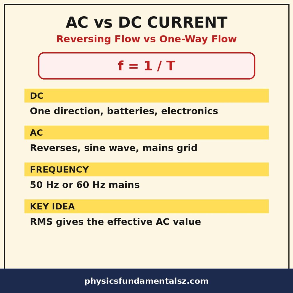
A graph of AC against time is a sine wave. It rises to a positive peak, falls through zero to a negative trough, and returns to zero. One full wave is one cycle. The number of cycles per second is the frequency, measured in hertz (Hz). Mains frequency is 50 Hz in the UK, Europe, Australia, and much of the world, and 60 Hz in North America and parts of South America and Asia.
AC comes from generators. A coil rotating in a magnetic field produces an induced voltage that reverses as the coil turns. Each half-turn reverses the direction of the induced current. The result is a sine wave whose frequency matches the rotation rate. HyperPhysics shows the rotating-coil generator diagrams that produce this sine wave. Our guide to electromagnetic induction explains how generators and transformers use this effect.
AC vs DC at a Glance
| Feature | DC (Direct Current) | AC (Alternating Current) |
|---|---|---|
| Direction of flow | One direction only | Reverses periodically |
| Graph against time | Horizontal straight line | Sine wave (usually) |
| Frequency | Zero (no cycles) | 50 Hz or 60 Hz for mains supply |
| Voltage value | Steady (ideally constant) | Varies; quoted as RMS value |
| Main sources | Batteries, cells, solar panels | Generators, alternators, mains grid |
| Transmission over distance | Losses harder to manage at low voltage; HVDC used for special links | Easy to step up with transformers, so efficient over long distances |
| Storage | Stored in batteries and capacitors | Cannot be stored directly; must be converted to DC first |
| Typical uses | Phones, laptops, torches, electric vehicles, electronics | Homes, factories, power grids, large motors |
| Skin effect and reactance | No reactance; simple resistance only | Inductors and capacitors add reactance |
| Safety note | Lower shock risk at low voltage, but high-voltage DC is dangerous | Mains AC is dangerous; let-go threshold and frequency effects matter |
This table covers the points examiners test most. Learn the direction row, the graph row, and the transmission row first. Those three rows answer the majority of comparison questions.
Waveforms: Seeing the Difference
The waveform is the most reliable way to tell AC from DC. A cathode-ray oscilloscope, or a modern digital scope, plots voltage or current against time. The pattern on the screen identifies the current type at once.
DC gives a flat trace. Switch the supply on, and the trace jumps to a steady height and stays there. Switch it off, and the trace falls to zero. There is no repeating pattern, because nothing alternates.
AC gives a repeating wave. For mains electricity, the wave is sinusoidal. Its peak value is higher than the quoted RMS value, a point explained in the next section. The wave crosses zero twice per cycle. At those instants, the current is momentarily zero, even though energy delivery continues on average.
Other waveforms exist in electronics. Square waves drive digital circuits. Triangular and sawtooth waves appear in signal processing. Pulsed DC appears in motor controllers. In school and college physics, however, AC almost always means a sine wave, and DC almost always means a steady value. State that assumption if a question leaves the waveform unclear.
Frequency and period describe the AC wave. Period T is the time for one cycle. Frequency f is the number of cycles per second. They are reciprocals: f = 1 ÷ T. For 50 Hz mains, the period is 1 ÷ 50 = 0.02 s, or 20 milliseconds. Each half-cycle, with one direction of flow, lasts 10 milliseconds.
Key AC Quantities: Peak, RMS, and Average
AC values need care, because the current changes at every instant. Three quantities matter: peak value, RMS value, and average value. Confusing them is a common source of lost marks.
The peak value, I₀ or V₀, is the maximum value reached in each cycle. It is the height of the sine wave. For UK mains at 230 V RMS, the peak voltage is about 325 V. Equipment insulation must withstand the peak, not just the RMS value.
The RMS value, root mean square, is the effective value. An AC supply with an RMS voltage of 230 V delivers the same average power to a resistor as a 230 V DC supply. Mains voltages are always quoted as RMS values. The relationship for a sine wave is V rms = V₀ ÷ √2, or about 0.707 × V₀. The same rule applies to current.
The average value of a full sine wave over one cycle is zero, because positive and negative halves cancel. That zero average does not mean zero power. Power depends on the square of current, and squares are always positive. RMS exists precisely to give a meaningful average power value. Always use RMS values in AC power calculations unless a question states otherwise.
Phase adds another layer in AC circuits. Voltage and current may peak at different times when inductors or capacitors are present. That time shift is the phase difference. It affects power delivery and is a key idea in advanced AC theory, though school questions usually assume voltage and current are in phase for a pure resistor.
How AC Is Generated
Most of the world’s electricity starts as AC. A generator rotates a coil in a magnetic field, or rotates a magnet near a coil. As the coil turns, the magnetic flux through it changes. That change induces a voltage, following Faraday’s law of induction.
The induced voltage reverses each half-turn. When the coil’s orientation flips relative to the field, the induced current flips with it. The output is therefore a sine wave, with a frequency set by the rotation speed and the number of pole pairs. Power stations control frequency carefully, because the whole grid must stay synchronised.
Turbines drive the generators. Steam turbines use heat from coal, gas, or nuclear reactions. Water turbines use falling water in hydroelectric plants. Wind turbines use moving air directly. The energy source differs, but the generator principle is the same. Mechanical rotation becomes alternating electrical energy.
Three-phase AC dominates large-scale generation and distribution. Three coils, offset by 120 degrees, produce three sine waves. Together they deliver smoother, more constant power than single-phase AC. Factories and large motors use three-phase supply. Homes normally receive one phase from the three-phase system.
Transformers: AC’s Decisive Advantage
A transformer changes AC voltage from one level to another. It has two coils wound on a shared iron core. Changing current in the primary coil creates a changing magnetic flux. That flux induces a voltage in the secondary coil. No moving parts are involved, and no electrical connection exists between the coils.
Transformers only work with changing current. A steady DC current creates a steady magnetic field, which induces no voltage in the secondary coil. That single fact explains why AC dominates power distribution. AC can be stepped up and down easily. DC, historically, could not.
The turns ratio sets the voltage ratio. If the secondary coil has ten times as many turns as the primary, the output voltage is ten times the input voltage, ignoring losses. Power is conserved in an ideal transformer, so stepping voltage up steps current down by the same factor. Lower current means lower heating losses in transmission lines, since heating depends on current squared times resistance.
Power is therefore transmitted at very high voltages, often hundreds of kilovolts, and stepped down near homes and businesses. The grid is a chain of transformers, each matching voltage to its part of the journey. Our guide to power in electrical circuits explains the power and heating relationships behind this design.
Modern power electronics have changed the picture partly. High-voltage DC (HVDC) links now carry power over very long distances and under the sea, using converter stations at each end. HVDC avoids some AC losses and needs no synchronisation between grids. Even so, AC remains the standard for generation and local distribution, and HVDC links convert back to AC for delivery.
How DC Is Produced and Converted
Batteries produce DC by chemical action. Inside a cell, chemical reactions separate charge and maintain a potential difference between terminals. Connect a circuit, and charge flows one way until the chemicals are exhausted or the cell is recharged. Rechargeable cells reverse the reactions with an external DC supply.
Solar cells produce DC by the photovoltaic effect. Photons free charge carriers in a semiconductor, and the cell structure sweeps them in one direction. A solar panel’s output is DC, which an inverter converts to AC for home use or grid export. The inverter switches the DC on and off in a controlled pattern to build a sine-like wave.
Rectifiers convert AC to DC. A diode allows current in one direction only. A single diode gives half-wave rectification, using only half of each AC cycle. A bridge of four diodes gives full-wave rectification, using both halves. A smoothing capacitor then fills the gaps, producing a steadier DC output. All About Circuits explains half-wave and full-wave rectifier circuits with diagrams and worked examples. Every phone charger contains a rectifier and a smoothing stage.
Inverters do the reverse. They convert DC to AC by switching the DC supply rapidly and filtering the result into a sine wave. Electric vehicles use inverters to drive AC motors from a DC battery. Solar systems use inverters to feed AC into homes and grids. The two conversions, rectify and invert, link the AC and DC worlds.
How Components Behave: Resistors, Inductors, Capacitors
Resistors behave the same way in AC and DC circuits, apart from the need to use RMS values for AC power. Ohm’s law applies to instantaneous values and to RMS values alike, for a pure resistor. Heat is produced in both cases, at a rate given by P = I²R using RMS current for AC.
Inductors behave differently. An inductor opposes changes in current. In a DC circuit, after the switch-on transient, an ideal inductor acts like a plain wire. In an AC circuit, it presents inductive reactance, which grows with frequency. The formula is X L = 2πfL, where L is inductance. Inductors also shift current behind voltage in phase.
Capacitors behave in the opposite way. A capacitor blocks DC completely once charged, because its plates are separated by an insulator. In an AC circuit, it charges and discharges each half-cycle, allowing current to flow. Capacitive reactance falls as frequency rises: X C = 1 ÷ (2πfC). Capacitors shift current ahead of voltage in phase.
These differences matter in circuit design. Filters use inductors and capacitors to pass some frequencies and block others. Motors use inductance for their magnetic fields. Power-factor correction uses capacitors to offset inductive loads. None of this behaviour appears in a pure DC circuit, where frequency is effectively zero.
Impedance, symbol Z, is the AC equivalent of resistance. It combines resistance and reactance, accounting for phase shifts. In DC circuits, impedance reduces to resistance alone. The general form of Ohm’s law for AC is V = IZ, using RMS values and allowing for phase.
Worked Calculations
Calculation 1: Peak Voltage from RMS
UK mains voltage is quoted as 230 V RMS. Find the peak voltage, assuming a sine wave.
V₀ = V rms × √2 = 230 × 1.414 ≈ 325 V. The peak is much higher than the quoted value. Insulation, component ratings, and safety testing must handle 325 V, not merely 230 V. The same factor applies to current: I₀ = I rms × √2.
Calculation 2: Period of Mains AC
Find the period of a 50 Hz supply, and the duration of one half-cycle.
T = 1 ÷ f = 1 ÷ 50 = 0.02 s. One full cycle lasts 20 ms. One half-cycle, with current in a single direction, lasts 10 ms. At 60 Hz, the period is about 16.7 ms. These short times explain why AC flicker in lights is invisible to the eye.
Calculation 3: DC Power
A 12 V battery drives a 3 A current through a resistor. Find the power dissipated.
P = VI = 12 × 3 = 36 W. Equivalently, P = I²R, with R = V ÷ I = 4 Ω, giving P = 9 × 4 = 36 W. The calculation is direct, because DC values are steady.
Calculation 4: AC Power in a Resistor
A resistor carries an RMS current of 2 A from a 230 V RMS supply. Find the average power.
P = V rms × I rms = 230 × 2 = 460 W, for a pure resistor where voltage and current are in phase. Using peak values without the RMS conversion would overstate the power by a factor of two. Always check whether given AC values are RMS or peak before calculating.
Calculation 5: Transformer Step-Up
A transformer has 100 turns on the primary coil and 2,000 turns on the secondary. The primary voltage is 230 V RMS. Find the secondary voltage, ignoring losses.
Voltage ratio equals turns ratio. V secondary = 230 × (2,000 ÷ 100) = 230 × 20 = 4,600 V. This is a step-up transformer. In a real grid, step-up ratios are far larger, taking voltage to hundreds of kilovolts for transmission.
Where AC and DC Are Used
AC dominates wherever power is generated, transmitted, or used in bulk. Homes receive AC. Offices, factories, and street lighting run on AC. Large induction motors, heaters, and industrial machines are AC devices. The grid itself is an AC system from generator to substation.
DC dominates wherever energy is stored or electronics are involved. Batteries store DC. Phones, tablets, laptops, and most gadgets run on DC internally. Electric vehicles store DC in battery packs, even when their motors run on AC through an inverter. Torches, toys, and remote controls use DC cells.
Some systems mix both deliberately. A laptop charger takes AC from the wall and delivers DC to the laptop. A solar home generates DC, inverts it to AC for the house, and may store surplus in a DC battery. An electric train may draw AC from overhead lines and convert it for DC traction motors, or vice versa. The boundary between AC and DC is a converter, not a wall.
Emerging uses blur the line further. Data centres increasingly consider DC distribution to cut conversion losses. HVDC links already move bulk power between regions. USB-C Power Delivery has made low-voltage DC a universal standard for small devices. The grid stays AC, but DC is growing at its edges.
| Application | AC or DC | Reason |
|---|---|---|
| Home wall sockets | AC | Grid distribution and transformers |
| Phone and laptop charging | DC at the device | Batteries and electronics need steady supply |
| Electric vehicle battery | DC storage | Batteries store charge chemically |
| Electric vehicle motor | Usually AC via inverter | Efficient, robust motor control |
| Solar panels | DC output | Photovoltaic effect drives one-way flow |
| Power stations | AC output | Generators produce sine waves naturally |
| Long-distance undersea cables | Often HVDC | Lower losses and no synchronisation needed |
| Electroplating and welding | DC | Steady one-way current deposits metal evenly |
Advantages and Disadvantages
AC’s main advantage is transmission. Transformers step voltage up for efficient long-distance travel and down for safe use. Generation is also simple, because rotating generators naturally produce sine waves. AC motors are rugged, cheap, and widely available, with no brushes to wear out in induction designs.
AC’s disadvantages include complexity in circuit analysis. Reactance, phase, and power factor must be considered. Skin effect pushes high-frequency AC toward the surface of conductors, raising effective resistance. AC cannot be stored directly, so every stored-energy system needs conversion.
DC’s main advantage is simplicity and storage. Values are steady, analysis is direct, and batteries store DC naturally. Electronics, motors with precise speed control, and electroplating all favour DC. Low-voltage DC is also convenient and relatively safe for small devices.
DC’s disadvantages centre on transmission and conversion. Historically, changing DC voltage was hard, which made long-distance DC transmission impractical. Modern converters have eased that problem, but converter stations are expensive. High-voltage DC switching is also harder than AC switching, because AC current passes through zero each half-cycle, helping circuit breakers interrupt it.
The historical “War of the Currents” in the late nineteenth century turned on these trade-offs. Edison backed DC distribution, while Tesla and Westinghouse backed AC. AC won for distribution, because transformers solved the transmission problem. A century later, power electronics have reopened parts of the contest, and both systems now coexist.
Safety: Respect Both Types
Mains AC is dangerous and must be treated with respect. A 230 V RMS supply peaks at about 325 V, and it can drive a lethal current through the body. AC at mains frequency can interfere with the heart’s rhythm and can cause muscles to grip, making it hard to let go of a live conductor. Never work on mains wiring unless qualified and the supply is isolated.
DC is not automatically safe. Low-voltage DC from batteries and USB supplies is low risk, but high-voltage DC is dangerous too. Large battery packs in electric vehicles store great energy and can deliver huge currents. Short circuits can cause burns, fires, and arc flashes in either system.
General safety rules apply to both. Isolate the supply before working on a circuit. Use insulated tools and rated test equipment. Never bypass fuses or protective devices. Keep water away from electrical equipment. If someone receives an electric shock, do not touch them while they are still in contact with the supply; isolate the power first and call for help.
In the lab, check meter settings before measuring. AC and DC ranges on a multimeter are different, and using the wrong range gives a wrong reading. Check that a supply is DC or AC before connecting a component that cares about direction, such as an LED or an electrolytic capacitor. The Physics Classroom circuit tutorials reinforce the same safe-measurement habits for school and college labs. A moment of checking prevents damaged equipment.
AC and DC in Circuits: Series, Parallel, and Kirchhoff’s Laws
Kirchhoff’s laws apply to both AC and DC circuits. The current law, that charge is conserved at a junction, holds at every instant. The voltage law, that voltages around a closed loop sum to zero, also holds at every instant. In AC circuits, the laws apply to instantaneous values, RMS values with phase, or phasor quantities, depending on the analysis method.
Series and parallel rules for resistors are the same in both systems. Resistors in series add directly. Resistors in parallel combine by reciprocal addition. Our guides to series and parallel circuits and resistors in series and parallel cover the DC cases in full, and the resistor rules carry over to AC with RMS values.
Capacitors and inductors follow different combination rules, and their AC behaviour depends on frequency. Two capacitors in series combine like resistors in parallel, and vice versa. These details belong to advanced circuit theory, but the pattern is worth noting: reactive components do not behave like resistors, and their combinations need their own rules.
Circuit analysis in AC often uses phasors, rotating arrows that represent sine waves. A phasor’s length shows amplitude, and its angle shows phase. Adding phasors is vector addition, which handles phase shifts cleanly. School questions rarely require phasors, but recognising the term helps when reading further.
Common Mistakes to Avoid
The most common mistake is saying AC current “goes back and forth to the power station”. Charge carriers oscillate locally. Energy flows from station to load through the fields. The electrons in your home wiring do not travel to the power station and back. Their drift is a small oscillation about a mean position.
A second mistake is using peak values in power formulas. AC power uses RMS values. Peak voltage is √2 times the RMS value for a sine wave, and mixing them up gives a wrong power by a factor of two. Check every AC value’s label before calculating.
A third mistake is claiming transformers work with DC. They do not, except for a brief pulse when DC is switched on or off. A steady DC current gives a steady flux, which induces nothing. If a question asks why the grid uses AC, the transformer answer is the key.
A fourth mistake is saying DC has no frequency. DC is often described as having zero frequency, which is a useful convention. It means no cycles occur. Do not confuse this with “no current”. DC carries a steady current at zero frequency, in the same way a stationary object has zero velocity but still exists.
A fifth mistake is assuming all “AC” waveforms are sine waves. Mains AC is sinusoidal, but electronics use square, triangular, and pulsed waveforms too. In exam questions, assume a sine wave unless told otherwise, and state the assumption if the question is ambiguous.
Expert Tips for Exams
Draw the waveform first. A flat line means DC. A sine wave means AC. Sketching the graph often answers a question before any calculation begins. Label the axes with quantity and time, and mark peak values on AC sketches.
Quote RMS values for mains questions. If a question gives 230 V without qualification, treat it as RMS. If it gives a peak value, say so in your working and convert before using power formulas. Examiners check for this distinction explicitly.
Learn the transformer ratio and the RMS relationship as a pair. V secondary ÷ V primary = N secondary ÷ N primary, and V rms = V₀ ÷ √2. Together they answer most AC calculation questions at school level. Add f = 1 ÷ T for frequency and period questions.
Explain choices with reasons, not just labels. “Homes use AC because transformers allow efficient transmission at high voltage” earns more credit than “homes use AC”. “Phones use DC because batteries store DC and chips need a steady supply” beats “phones use DC” alone.
Practise converting between peak and RMS until it is automatic. Also practise reading oscilloscope traces, including time-base and voltage-scale calculations. Trace questions combine graph skills with AC theory, and they appear regularly.
Frequently Asked Questions
What is the main difference between AC and DC current?
DC flows in one direction at a steady value. AC reverses direction repeatedly, usually as a sine wave. DC comes from batteries and solar panels. AC comes from generators and the mains grid.
Which is more dangerous, AC or DC?
Both can be dangerous at high voltage or high current. Mains AC is particularly hazardous because its frequency can disrupt heart rhythm and cause muscles to grip. High-voltage DC from large battery systems is also lethal. Treat both with respect and never work on live circuits unless qualified.
Why do homes use AC instead of DC?
AC can be stepped up and down with transformers, making long-distance transmission efficient. Power is sent at high voltage and low current to reduce heating losses, then stepped down for safe home use. DC could not be transformed easily when grids were built.
Can AC be stored in a battery?
No, not directly. Batteries store DC through chemical reactions. AC must be rectified to DC before it can charge a battery. To use stored energy as AC, an inverter converts the battery’s DC back to AC.
What is the frequency of AC mains electricity?
Mains frequency is 50 Hz in the UK, Europe, Australia, and much of the world. It is 60 Hz in North America and parts of South America and Asia. Frequency is the number of full cycles per second, measured in hertz.
What does RMS mean in AC circuits?
RMS stands for root mean square. It is the effective value of an AC quantity. An AC supply at 230 V RMS delivers the same average power to a resistor as a 230 V DC supply. For a sine wave, RMS value equals peak value divided by √2.
What is the peak voltage of 230 V mains?
About 325 V. Peak value = RMS value × √2, so 230 × 1.414 ≈ 325 V. Equipment and insulation must withstand the peak, even though the supply is quoted as 230 V RMS.
Do transformers work with DC?
No, not with steady DC. Transformers need a changing magnetic flux to induce voltage in the secondary coil. Steady DC gives a steady flux and induces nothing, apart from a brief pulse when switched on or off. This is why the grid uses AC.
What devices use DC current?
Phones, laptops, tablets, torches, toys, remote controls, and electric vehicle batteries all use DC. Most electronic circuits run on DC, even when they plug into AC wall sockets through a charger or power supply.
What devices use AC current?
Homes, offices, factories, and street lighting run on AC. Large motors, heaters, washing machines, and air conditioners are typically AC devices. The power grid itself is an AC system.
How is AC converted to DC?
A rectifier converts AC to DC, using diodes that allow current in one direction only. A smoothing capacitor then steadies the output. Phone chargers, laptop adapters, and power supplies all contain rectifiers.
How is DC converted to AC?
An inverter converts DC to AC by switching the DC supply rapidly and filtering the result into a sine wave. Solar systems and electric vehicles use inverters. A solar inverter feeds AC into a home or the grid from DC panels.
What is a sine wave in AC?
A sine wave is a smooth, repeating wave that rises to a positive peak, falls through zero to a negative trough, and returns to zero. Mains AC follows this shape. Its smoothness makes it ideal for generation with rotating machines and for transformer operation.
Why does AC have a frequency but DC does not?
Frequency counts cycles per second. AC repeats a cycle, so it has a frequency, such as 50 Hz. DC does not cycle, so it is described as zero frequency. The steady DC value is the whole story, with no repeating wave to count.
Can DC power be transmitted over long distances?
Yes, with modern HVDC technology. High-voltage DC links carry power over very long distances and under the sea, with converter stations at each end. HVDC avoids some AC losses and needs no synchronisation. AC still dominates local distribution.
What is the difference between AC voltage and DC voltage?
DC voltage is steady and has a fixed polarity. AC voltage varies with time, reverses polarity each half-cycle, and is quoted as an RMS value. A voltmeter on an AC range reads RMS voltage, while a DC range reads the steady value.
Why do electronics need DC?
Transistors and chips need a stable supply with defined positive and negative terminals. Reversing polarity can damage components or stop them working. DC gives that stable, one-way supply, which is why chargers convert AC to DC.
What is three-phase AC?
Three-phase AC uses three sine waves offset by 120 degrees. Together they deliver smoother power than single-phase AC. Power stations generate three-phase power, factories use it for large motors, and homes normally receive one of the three phases.
Conclusion
AC and DC differ in direction, waveform, and behaviour, and each difference has a practical reason. DC flows one way, stays steady, stores easily, and suits electronics. AC reverses in a sine wave, transforms easily, transmits efficiently, and suits the power grid.
The transformer is the pivot of the whole story. It works only with changing current, so it ties the grid to AC. The battery is the other pivot. It stores charge chemically, so it ties portable power to DC. Rectifiers and inverters bridge the two worlds wherever they meet.
Learn the waveforms, the RMS rule, and the transformer rule, and most AC versus DC questions become straightforward. Then look around your home and name the converter in each charger and adapter. Physics is memorable when you can see it working on your desk.
For your next step, revise electric current and Ohm’s law. Then read our guide to electromagnetic induction to see how generators produce the AC sine wave in the first place.