Resistors in Series and Parallel: Formulas, Rules & Worked Examples
Every circuit you’ve ever touched — a flashlight, a string of LED lights, the dashboard of a car — relies on resistors working together in one of two basic arrangements: Resistors in Series and Parallel.
Get these two configurations right, and you can analyze almost any DC circuit you’ll ever encounter.
Table of Contents
Quick Answer: Resistors in Series and Parallel
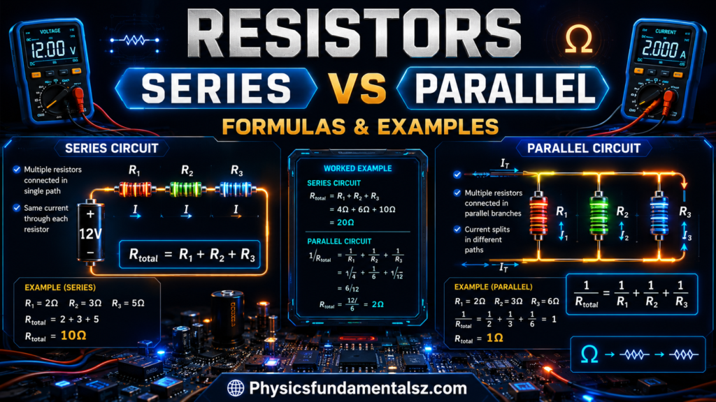
- Series resistors: total resistance = the sum of all individual resistances. Current is the same through every resistor; voltage divides between them.
- Parallel resistors: total resistance is found using the reciprocal formula and is always lower than the smallest individual resistor. Voltage is the same across every resistor; current divides between them.
| Property | Series Circuit | Parallel Circuit |
|---|---|---|
| Current | Same through every resistor | Divides across each branch |
| Voltage | Divides across each resistor | Same across every resistor |
| Total resistance | Sum of all resistances (always increases) | Reciprocal formula (always decreases) |
| Formula | R_total = R1 + R2 + R3 + … | 1/R_total = 1/R1 + 1/R2 + 1/R3 + … |
| If one component fails (open) | Entire circuit stops | Other branches keep working |
| Typical real-world use | Old-style string lights, current-limiting setups | Household wiring, LED arrays, power distribution |
What Are Resistors in Series?
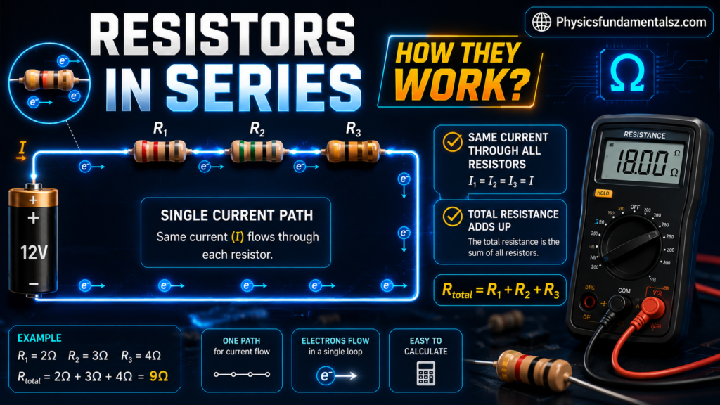
Resistors are in series when they’re connected end-to-end along a single path, so the same current has to flow through each one in sequence before reaching the next component. There’s no branching — just one continuous loop.
Series Circuit Formula
For any number of resistors connected in series, the total (equivalent) resistance is simply the sum of each individual resistance:
R_total = R1 + R2 + R3 + … + Rn
Because resistance only adds up, total resistance in a series circuit is always higher than any single resistor in the chain.
Key Characteristics of Series Circuits
- Current is identical at every point in the circuit — there’s only one path for it to take.
- Voltage divides among the resistors, proportional to each resistor’s value (this is the basis of the voltage divider rule).
- Total resistance increases every time you add another resistor.
- If one resistor fails open, the entire circuit stops working — this is why old-style Christmas lights (wired in series) would go completely dark if a single bulb burned out.
Worked Example: Resistors in Series
Three resistors — 2 Ω, 3 Ω, and 6 Ω — are connected in series across a 4V supply.
- Total resistance: R_total = 2 + 3 + 6 = 11 Ω
- Total current (Ohm’s Law, I = V/R): I = 4V / 11Ω ≈ 0.36 A
- Voltage drop across each resistor (V = IR):
- V1 = 0.36 × 2 ≈ 0.73 V
- V2 = 0.36 × 3 ≈ 1.09 V
- V3 = 0.36 × 6 ≈ 2.18 V
- Check: 0.73 + 1.09 + 2.18 ≈ 4.00 V ✓ (matches the source voltage, confirming the calculation)
What Are Resistors in Parallel?
Resistors are in parallel when both ends of each resistor connect to the same two shared points (nodes) in the circuit. Instead of one path, current now has multiple branches it can take simultaneously.
Parallel Circuit Formula
For resistors in parallel, you use the reciprocal formula:
1 / R_total = 1/R1 + 1/R2 + 1/R3 + … + 1/Rn
For just two resistors, there’s a handy shortcut:
R_total = (R1 × R2) / (R1 + R2)
Because you’re combining multiple paths for current, total resistance in a parallel circuit is always lower than the smallest individual resistor in the group.
Key Characteristics of Parallel Circuits
- Voltage is identical across every resistor — each branch connects directly to the same two nodes.
- Current splits between the branches, with more current flowing through lower-resistance paths (this is the current divider rule).
- Total resistance decreases every time you add another parallel branch, since you’re opening up more paths for current to flow.
- If one resistor fails open, the other branches keep working — this is why household outlets, appliances, and modern LED strings are wired in parallel.
Worked Example: Resistors in Parallel
Three resistors — 100 Ω, 50 Ω, and 20 Ω — are connected in parallel.
- Apply the reciprocal formula: 1/R_total = 1/100 + 1/50 + 1/20 = 0.01 + 0.02 + 0.05 = 0.08
- Take the reciprocal of that sum: R_total = 1 / 0.08 = 12.5 Ω
Notice that 12.5 Ω is lower than even the smallest resistor (20 Ω) in the group — that’s the defining signature of a parallel network.
Series vs. Parallel Resistors: Side-by-Side Comparison
| Factor | Series | Parallel |
|---|---|---|
| Current path | Single path | Multiple paths |
| Current value | Same throughout | Divides by branch |
| Voltage behavior | Divides across resistors | Same across all resistors |
| Effect of adding resistors | Increases total resistance | Decreases total resistance |
| Formula complexity | Simple addition | Reciprocal (harder by hand) |
| Fault tolerance | Low — one failure breaks circuit | High — other branches keep working |
| Common real-world example | Older string lights, fuses in a line | House wiring, car headlights, LED arrays |
How to Identify Series vs. Parallel Resistors in a Circuit

A quick way to tell them apart when reading a circuit diagram:
- Series: Trace the current path. If it flows through one resistor, then directly into the next, with no other branch to take, they’re in series.
- Parallel: Look for two resistors whose leads connect to the exact same two points (nodes) in the circuit. If both ends match up, they’re in parallel.
- Neither obvious: Many real circuits are a combination of both — see the next section.
Combination (Series-Parallel) Circuits
Most real circuits aren’t purely series or purely parallel — they’re a mix of both, often called series-parallel or mixed resistor networks.
Step-by-Step Method to Simplify Mixed Circuits
- Scan the circuit and identify any resistors that are clearly in series (same current path, no branching).
- Combine that series group into a single equivalent resistance using R_total = R1 + R2.
- Identify resistors that are clearly in parallel (same two nodes) and combine them using the reciprocal formula.
- Redraw the simplified circuit with the combined resistances in place of the original groups.
- Repeat steps 1–4 until you’re left with a single equivalent resistance for the whole circuit.
Worked Example: Series-Parallel Combination
Suppose R1 = 100 Ω is in series with a parallel combination of R2 = 200 Ω and R3 = 300 Ω.
- Combine the parallel group first (R2 and R3): 1/R_parallel = 1/200 + 1/300 = 0.005 + 0.00333 = 0.00833 R_parallel = 1 / 0.00833 ≈ 120 Ω
- Add the series resistor: R_total = R1 + R_parallel = 100 + 120 = 220 Ω
This two-step “reduce the parallel group, then add the series resistor” technique works for circuits of almost any complexity — just keep reducing one group at a time.
Why Parallel Resistance Is Always Less Than the Smallest Resistor
This trips up a lot of beginners, but the intuition is straightforward: adding a resistor in parallel doesn’t remove any existing path for current — it adds a brand-new one. More available paths means more total current can flow for the same voltage, and since resistance is a measure of opposition to that current, more current at the same voltage means lower overall resistance. No matter how large the new resistor is, it can only add current, never subtract it — so total resistance can only go down, never up.
Voltage and Current Behavior
Voltage Divider Rule
In a series circuit, each resistor’s share of the total voltage is proportional to its resistance relative to the total:
V_x = V_source × (R_x / R_total)
This is why series resistors are commonly used to scale down a voltage to a specific level for a sensor or reference circuit.
Current Divider Rule
In a parallel circuit with two resistors, the current through one branch is:
I_x = I_total × (R_other / (R1 + R2))
Lower-resistance branches always carry more current — current takes the path of least resistance, though it never abandons the higher-resistance path entirely.
Real-World Applications
- Household wiring — outlets and light switches are wired in parallel so every device gets full voltage and can operate independently.
- String lights — modern LED strings use parallel wiring so one bulb failing doesn’t take down the whole strand (unlike older series-wired sets).
- LED current-limiting resistors — a resistor placed in series with an LED protects it from excess current.
- Automotive headlights — wired in parallel so each headlight receives full battery voltage.
- Sensor and reference circuits — voltage dividers (series resistors) are used to scale signals for microcontrollers.
- Power distribution systems — parallel connections let multiple devices draw from the same voltage source independently.
Common Mistakes to Avoid
- Forgetting to take the reciprocal at the end of the parallel formula — you calculate 1/R_total, not R_total directly.
- Adding parallel resistors like series resistors (a very common beginner error).
- Assuming voltage is shared in a parallel circuit — it isn’t; voltage is the same across all branches, current is what divides.
- Assuming current is shared in a series circuit — it isn’t; current is the same everywhere, voltage is what divides.
- Not simplifying step by step in mixed circuits — trying to solve everything in one pass instead of reducing one group at a time.
- Ignoring power ratings — an equivalent resistance calculation tells you resistance, not whether each resistor can safely handle the resulting current and heat.
Practice Problems

- Three resistors of 5 Ω, 10 Ω, and 15 Ω are in series across a 24V source. Find the total resistance and the voltage drop across each resistor.
- Two resistors, 40 Ω and 60 Ω, are connected in parallel. What is the equivalent resistance?
- A 10 Ω resistor is in series with a parallel pair of 20 Ω and 30 Ω resistors. Find the total resistance of the network.
- Four identical 100 Ω resistors are connected in parallel. What is the total resistance?
- A series circuit has a total resistance of 50 Ω and carries 2 A. What is the source voltage?
Frequently Asked Questions (FAQs)
What is the formula for resistors in series?
R_total = R1 + R2 + R3 + … — simply add up every resistance in the chain.
What is the formula for resistors in parallel?
1/R_total = 1/R1 + 1/R2 + 1/R3 + …, then take the reciprocal of that sum to get R_total.
How do you calculate total resistance in a series-parallel circuit?
Reduce the circuit step by step: combine any clearly parallel groups first, then add the result to the series resistors, repeating until one equivalent resistance remains.
Why does adding resistors in parallel decrease total resistance?
Because each new resistor adds another path for current to flow, and more available paths always lowers the overall opposition to current.
Why does adding resistors in series increase total resistance?
Because current has to push through every resistor one after another, and each additional resistor adds more opposition along that single path.
Is current the same in series or parallel circuits?
Current is the same through every component in a series circuit. In a parallel circuit, current divides across branches.
Is voltage the same in series or parallel circuits?
Voltage is the same across every branch in a parallel circuit. In a series circuit, voltage divides across the resistors.
How do you know if resistors are in series or parallel?
If current has only one possible path through them, they’re in series. If both ends of the resistors connect to the same two points, they’re in parallel.
What happens if one resistor fails in a series circuit?
The entire circuit opens and stops working, since there’s no alternate path for current.
What happens if one resistor fails in a parallel circuit?
The other branches continue operating normally, since each has its own independent path.
How many resistors can be connected in parallel?
There’s no fixed limit — the reciprocal formula works for any number of resistors, though practical circuit design and power limits apply.
What is the equivalent resistance of two equal resistors in parallel?
Exactly half of one resistor’s value (e.g., two 100 Ω resistors in parallel equal 50 Ω).
What is the equivalent resistance of two equal resistors in series?
Exactly double one resistor’s value (e.g., two 100 Ω resistors in series equal 200 Ω).
How do you calculate resistors with different values in parallel?
Use the full reciprocal formula: 1/R_total = 1/R1 + 1/R2 + …, then invert the result.
What is a series-parallel (mixed) circuit?
A circuit containing both series and parallel resistor groupings, solved by reducing each group step by step.
How do you simplify a complex resistor network?
Identify and combine the simplest series or parallel groups first, then treat each combined result as a single resistor and repeat.
What is the voltage divider rule?
It calculates each resistor’s share of total voltage in a series circuit: V_x = V_source × (R_x / R_total).
What is the current divider rule?
It calculates how much current flows through one branch of a parallel circuit relative to the other resistor’s value.
What is Ohm’s Law and how does it relate to resistor combinations?
Ohm’s Law (V = IR) lets you find voltage, current, or resistance once you know the other two — it’s the tool used at every step of series and parallel calculations.
What is Kirchhoff’s Voltage Law?
It states that the sum of voltage drops around any closed loop equals the total source voltage — the basis for analyzing series circuits.
What is Kirchhoff’s Current Law?
It states that the total current entering a node equals the total current leaving it — the basis for analyzing parallel circuits.
Why do household appliances use parallel wiring instead of series?
So every outlet and device receives full voltage and keeps working independently, even if another device is turned off or fails.
Why were old Christmas lights wired in series?
It was cheaper to manufacture, but it meant one burned-out bulb would darken the entire string — a major drawback compared to today’s parallel-wired sets.
How do resistors affect LED brightness in a circuit?
A series resistor limits current to the LED; too much resistance dims it, too little risks damaging the LED from excess current.
What is the power dissipated by a resistor in series vs. parallel?
Power depends on both current and voltage at each resistor (P = IV), which differ between series and parallel arrangements — so power dissipation must be calculated individually for each resistor.
Can resistors in parallel have different power ratings?
Yes, but each resistor must be rated to handle its own actual current and power dissipation, not just the total circuit power.
How do you convert conductance back to resistance?
Conductance (in siemens) is the reciprocal of resistance: R = 1/G.
Is total power the same in series and parallel circuits with equal resistors?
No — total power depends on the total resistance and applied voltage/current, which differ between series and parallel configurations even with identical resistor values.
What’s the shortcut formula for two resistors in parallel?
R_total = (R1 × R2) / (R1 + R2).
How do you calculate resistors in a Wheatstone bridge?
A Wheatstone bridge uses four resistors in a diamond arrangement and is balanced (zero current across the bridge) when R1/R2 = R3/R4 — it’s analyzed differently from simple series-parallel networks.
What happens to circuit resistance as you add more parallel branches?
Total resistance keeps decreasing, approaching zero as more branches are added (though never actually reaching it with finite resistors).
What’s the difference between a short circuit and a parallel circuit?
A short circuit is an unintended near-zero-resistance path; a parallel circuit is an intentional design with two or more resistive branches sharing the same voltage.
How do engineers decide between series and parallel resistor configurations?
It depends on the goal: series for current limiting and voltage division, parallel for maintaining full voltage across independent loads and for redundancy.
Can resistors be arranged in more than two levels of series-parallel combination?
Yes — complex networks can nest multiple series and parallel groups; solve them the same way, one group at a time, working from the innermost combination outward.
How does resistor tolerance affect calculated equivalent resistance?
A resistor’s actual value can vary within its tolerance rating (e.g., ±5%), so real-world equivalent resistance may differ slightly from the calculated theoretical value.
What tools can verify a calculated equivalent resistance?
A multimeter measures actual resistance directly; circuit simulation software can verify more complex networks before physical assembly.
What is the equivalent resistance formula for three or more resistors in parallel?
The same general reciprocal formula applies regardless of how many resistors: 1/R_total = 1/R1 + 1/R2 + 1/R3 + … + 1/Rn.
How do temperature changes affect resistor combinations?
Most resistors have a temperature coefficient, meaning their resistance shifts slightly with temperature — this affects the actual, not the theoretical, equivalent resistance.
What are common mistakes when calculating parallel resistance?
The most frequent error is stopping at the reciprocal sum instead of inverting it, followed by mixing up when to add directly versus when to use the reciprocal formula.
Key Takeaways
- Series: resistances add directly (R_total = R1 + R2 + …); current stays the same, voltage divides.
- Parallel: resistances combine via the reciprocal formula; voltage stays the same, current divides.
- Total resistance always increases in series and always decreases in parallel.
- Mixed circuits are solved by reducing series and parallel groups step by step until one equivalent resistance remains.
- Real circuits — from household wiring to LED strings — are built on these two fundamental configurations, so mastering them is the foundation for all further circuit analysis.