Difference Between Series and Parallel Circuits: Current, Voltage, and Resistance Explained

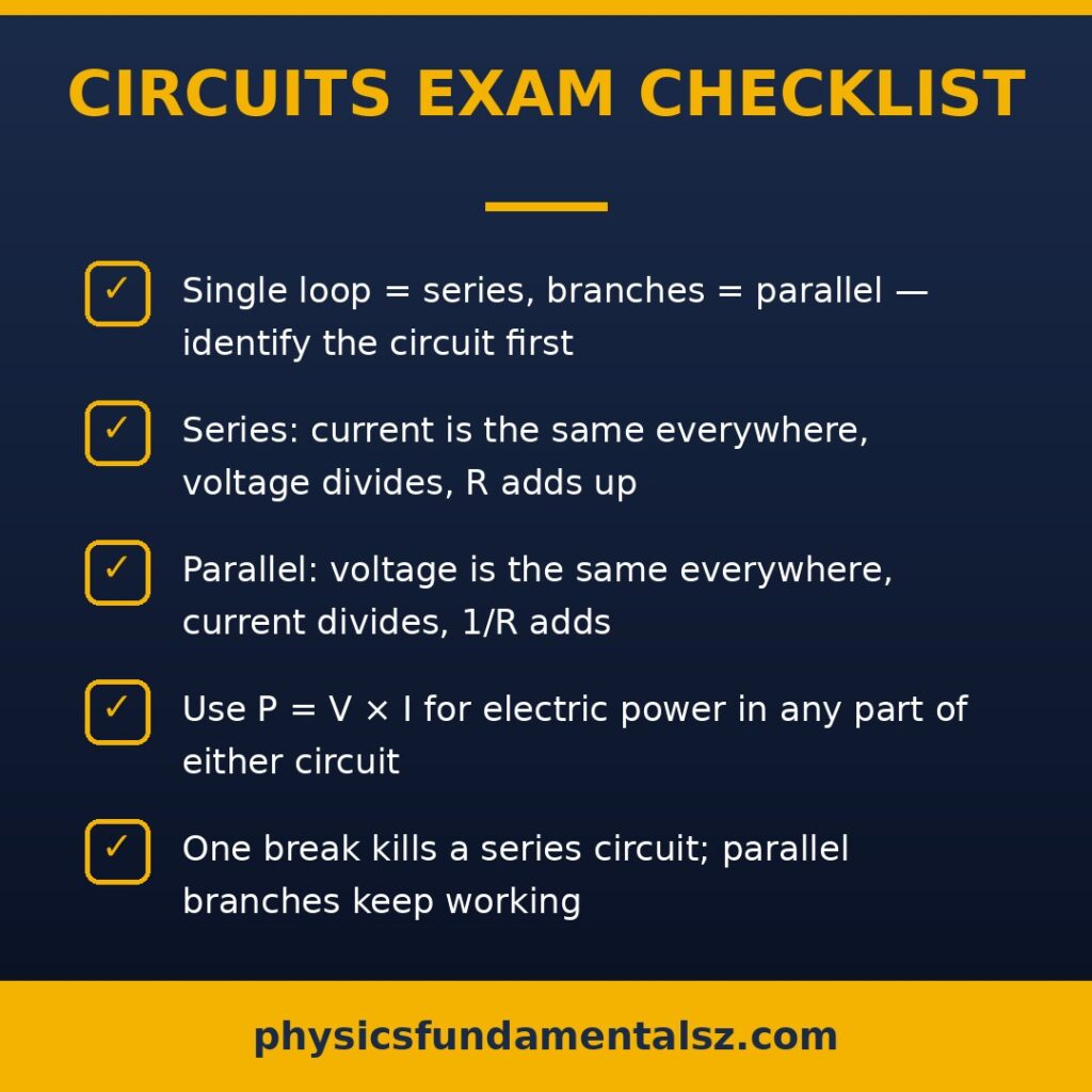
Quick answer: In a series circuit, components connect end-to-end in a single path — the same current flows through everything, but voltage divides. In a parallel circuit, components connect across the same two points in separate branches — voltage stays the same across every branch, but current divides. That one structural difference changes how current, voltage, resistance, and failure behave.
If you have ever wondered why one blown bulb kills a whole string of old Christmas lights but never kills the lights in your house, you already understand the practical difference between series and parallel circuits. In this guide you will learn exactly how the two circuit types work, the formulas that govern them, how to solve exam problems for each, and where each type is used in the real world.
What Is a Series Circuit?
A series circuit is a circuit in which components are connected end-to-end so that there is only one path for electric current to follow. The current that leaves the battery must pass through every component in turn before returning.
Think of a single-lane road: every car must drive past every checkpoint. If the road is blocked anywhere, nothing gets through.
Key properties of a series circuit
- Current is the same everywhere. Since there is only one path, charge has nowhere else to go: I_total = I_1 = I_2 = I_3.
- Voltage divides among components. The total voltage of the source equals the sum of the voltage drops: V_total = V_1 + V_2 + V_3.
- Resistance adds up. Total resistance is simply the sum: R_total = R_1 + R_2 + R_3. Adding more resistors makes the total resistance larger and the current smaller.
- One failure kills the circuit. Open the loop anywhere and current stops everywhere.
What Is a Parallel Circuit?
A parallel circuit is a circuit in which components are connected across the same two points, giving current multiple paths (branches) to follow. Each branch operates at the full source voltage.
Think of a river splitting into several streams around islands: water divides among the streams but every stream starts and ends at the same level.
Key properties of a parallel circuit
- Voltage is the same across every branch. Each branch connects directly across the source: V_total = V_1 = V_2 = V_3.
- Current divides among branches. The total current equals the sum of branch currents: I_total = I_1 + I_2 + I_3. More current flows through branches with less resistance.
- Resistance decreases. The total (equivalent) resistance is always less than the smallest branch resistance: 1/R_total = 1/R_1 + 1/R_2 + 1/R_3. Adding more branches gives current more paths, lowering total resistance.
- Branches are independent. If one branch opens, current keeps flowing through the others.
Series vs Parallel Circuits: Head-to-Head Comparison
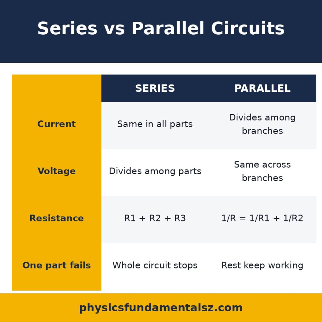
| Feature | Series Circuit | Parallel Circuit |
|---|---|---|
| Current | Same through all components (I_total = I_1 = I_2) | Splits among branches (I_total = I_1 + I_2 + I_3) |
| Voltage | Divides across components (V_total = V_1 + V_2 + V_3) | Same across every branch (V_total = V_1 = V_2) |
| Resistance | Adds up: R_total = R_1 + R_2 + R_3 | Reciprocal sum: 1/R_total = 1/R_1 + 1/R_2 + 1/R_3 |
| Total resistance trend | Increases as you add components | Decreases as you add branches |
| Effect of a break | Whole circuit stops working | Other branches keep working |
| Brightness of identical bulbs | Dimmer (voltage shared) | Full brightness (full voltage each) |
| Wiring complexity | Simple | More complex |
| Typical uses | Flashlights, old Christmas lights, fuses | Home wiring, car electrics, computer circuits |
Formulas You Need to Know
Series circuit formulas
- Equivalent resistance: R_eq = R_1 + R_2 + … + R_n
- Current (same everywhere): I = V_total / R_eq
- Voltage across resistor n: V_n = I × R_n (voltage divider)
Parallel circuit formulas
- Equivalent resistance: 1/R_eq = 1/R_1 + 1/R_2 + … + 1/R_n
- Voltage (same everywhere): V = V_total
- Current through branch n: I_n = V / R_n (current divider: branch current is inversely proportional to branch resistance)
Special case: two resistors in parallel
For two resistors, the reciprocal formula simplifies to the product-over-sum rule:
R_eq = (R_1 × R_2) / (R_1 + R_2)
Special case: N identical resistors
- N identical resistors R in series: R_eq = N × R
- N identical resistors R in parallel: R_eq = R / N
Worked Examples
Example 1: Series circuit calculation
Two resistors, 4 Ω and 6 Ω, are connected in series to a 20 V battery. Find the current and the voltage across each resistor.
Step 1 — total resistance: R_eq = 4 + 6 = 10 Ω
Step 2 — current: I = V / R_eq = 20 / 10 = 2 A (same through both resistors)
Step 3 — voltage drops: V_1 = I × R_1 = 2 × 4 = 8 V; V_2 = 2 × 6 = 12 V
Check: 8 + 12 = 20 V ✓
Example 2: Parallel circuit calculation
The same 4 Ω and 6 Ω resistors are connected in parallel to a 20 V battery. Find the total current.
Step 1 — voltage: each branch gets the full 20 V.
Step 2 — branch currents: I_1 = 20/4 = 5 A; I_2 = 20/6 ≈ 3.33 A
Step 3 — total current: I_total = 5 + 3.33 = 8.33 A
Check via R_eq: R_eq = (4 × 6)/(4 + 6) = 24/10 = 2.4 Ω; I = 20/2.4 = 8.33 A ✓
Notice the parallel combination draws far more current (8.33 A vs 2 A) — which is why adding parallel branches increases power demand.
Example 3: Which bulb is brighter?
Two identical bulbs are connected (a) in series and (b) in parallel to identical batteries. Which arrangement gives brighter bulbs?
In series, each bulb gets half the battery voltage, so each dissipates P = (V/2)²/R = V²/4R. In parallel, each bulb gets the full voltage, dissipating P = V²/R — four times the power. The parallel bulbs are much brighter. This is exactly why household lights are wired in parallel.
Combination Circuits (Series-Parallel)
Real circuits often mix both types. The strategy:
- Identify which resistors are purely in series or parallel with each other.
- Collapse each simple group into its equivalent resistance.
- Redraw the simplified circuit and repeat until one equivalent resistance remains.
- Work backwards to find branch currents and voltage drops.
Expert tip: Redraw the circuit so series sections run in a straight line and parallel branches are visibly stacked. Most “hard” combination problems become easy once the diagram is clean. On AP Physics exams, the majority of errors come from misreading the diagram, not from the math.
Common Mistakes to Avoid
- Assuming current divides in series. It never does — one path means one current.
- Assuming voltage divides in parallel. It never does — every branch sees full voltage.
- Adding reciprocals incorrectly. For parallel resistance, remember to take the reciprocal again at the end: compute 1/R_eq, then invert.
- Forgetting that parallel equivalent resistance is smaller than the smallest branch. If your answer is bigger, you made an error.
- Mixing up which quantity is “same.” Mnemonic: “Series shares Current, Parallel shares Potential (voltage)” — both start with the same letter pairs (S-C, P-P).
Real-World Applications
| Application | Circuit type | Why |
|---|---|---|
| Home wall outlets and lighting | Parallel | Every device gets full 120/230 V and works independently |
| Car headlights | Parallel | One burned-out headlight must not kill the other |
| Old-style Christmas lights | Series | Cheap wiring — but one dead bulb darkens the whole string |
| Flashlights | Series | Simple, compact, single current path |
| Fuses and circuit breakers | Series | Must carry (and interrupt) the entire circuit current |
| Solar panel arrays (shading resilience) | Parallel strings | A shaded panel does not choke the whole array |
| Ammeters | Series | Must measure the full current through a branch |
| Voltmeters | Parallel | Must measure across two points without disturbing current |
Key Takeaways
- Series: one path → same current, divided voltage, resistances add, one break kills all.
- Parallel: many paths → same voltage, divided current, equivalent resistance drops, branches are independent.
- Formulas: R_eq = R_1 + R_2 (series) vs 1/R_eq = 1/R_1 + 1/R_2 (parallel).
- Houses, cars, and electronics use parallel wiring for independence and full voltage; simple devices use series for simplicity.
- For combination circuits, collapse series/parallel groups step by step and redraw.
FAQs
1. What is the main difference between series and parallel circuits?
The main difference is the current path: a series circuit has a single path so current is the same everywhere but voltage divides, while a parallel circuit has multiple branches so voltage is the same across every branch but current divides.
2. Is voltage the same in a series circuit?
No. In a series circuit the total voltage divides among the components in proportion to their resistances (V = IR for each). Only the current stays the same throughout.
3. Why is current the same in a series circuit?
Because there is only one path, charge cannot accumulate or disappear at any point — whatever charge flows into a component must flow out. This is a direct consequence of the conservation of charge (Kirchhoff’s current law).
4. How do you calculate total resistance in a series circuit?
Add them directly: R_total = R_1 + R_2 + R_3 + …
5. How do you calculate total resistance in a parallel circuit?
Use the reciprocal formula: 1/R_total = 1/R_1 + 1/R_2 + 1/R_3 + …, then take the reciprocal of the result. For two resistors, use R_total = (R_1 × R_2)/(R_1 + R_2).
6. Which is brighter: bulbs in series or parallel?
Bulbs in parallel are brighter. Each parallel bulb receives the full battery voltage, while series bulbs share the voltage. Two identical bulbs in parallel each dissipate four times the power of the series arrangement.
7. Why are houses wired in parallel and not series?
Parallel wiring gives every outlet and light the full mains voltage and lets each device operate independently — turning off one lamp does not affect anything else. In series, one switched-off device would break the whole circuit.
8. What happens if one bulb burns out in a series circuit?
The circuit opens and all bulbs go out, because the single current path is broken. This is why old Christmas light strings went completely dark from one bad bulb.
9. What happens if one bulb burns out in a parallel circuit?
Nothing happens to the other branches — they keep working normally at full voltage. Only the total current drawn from the source decreases.
10. Can a circuit be both series and parallel?
Yes — these are called combination (series-parallel) circuits. Solve them by collapsing purely series or parallel groups into equivalent resistances step by step.
11. Does adding resistors in series increase or decrease current?
It decreases current. More series resistance means higher total resistance, and by Ohm’s law (I = V/R) the current from a fixed voltage source drops.
12. Does adding branches in parallel increase or decrease total resistance?
It decreases total resistance. More parallel paths give current more routes, so equivalent resistance falls — and total current from the source increases.
13. Where should an ammeter be connected: series or parallel?
In series with the component whose current you want to measure, so the full branch current flows through it. An ideal ammeter has near-zero resistance.
14. Where should a voltmeter be connected: series or parallel?
In parallel (across) the component whose voltage you want to measure. An ideal voltmeter has near-infinite resistance so it draws negligible current.
15. What is the product-over-sum rule?
For two resistors in parallel, R_eq = (R_1 × R_2)/(R_1 + R_2). It is a shortcut for the reciprocal formula and only works for exactly two resistors.
16. Why does a short circuit cause a large current?
A short creates a near-zero-resistance parallel path. Since total resistance collapses, current (I = V/R) spikes enormously, which is why fuses and breakers (wired in series) exist to interrupt it.
17. Do series circuits use more battery than parallel circuits?
For the same components, a parallel arrangement draws more total current and drains a battery faster, because its equivalent resistance is lower. Series circuits are more battery-friendly but deliver less power per component.
18. What is Kirchhoff’s voltage law in a series circuit?
The sum of voltage drops around any closed loop equals the source voltage (V_total = V_1 + V_2 + …). It is the formal statement of “voltage divides in series.”
19. How can you tell from a diagram if resistors are in series or parallel?
Trace the current: if the same current must flow through two resistors with no branching between them, they are in series. If both ends of two resistors connect to the same two nodes, they are in parallel.
20. Which circuit type is used in car batteries and why are fuses in series?
Car loads (lights, ignition, electronics) are wired in parallel so each gets full 12 V independently. Fuses are wired in series with the circuits they protect so they experience the full current and can break it during a fault.
External Authority Sources
- OpenStax University Physics Vol. 2, Chapter on DC circuits (openstax.org)
- The Physics Classroom: “Series Circuits” and “Parallel Circuits” (physicsclassroom.com)
- HyperPhysics, Georgia State University: DC circuits (hyperphysics.phy-astr.gsu.edu)
- Khan Academy: “Resistors in series and parallel” (khanacademy.org)
- College Board AP Physics 2 Course and Exam Description — electric circuits section