What Is Electromagnetic Induction? Explained Simply With Examples

Imagine moving a magnet near a coil of wire and watching a light bulb glow — without any battery connected. No wires touch the magnet. No power source feeds the coil. Yet electricity appears, seemingly out of nowhere.
That is electromagnetic induction, one of the most useful discoveries in the history of physics. It is the reason power stations can generate electricity, the reason your phone can charge wirelessly, and the reason transformers can step voltage up and down across the grid.
In this guide, you will learn exactly what electromagnetic induction is, the laws that govern it, the formulas you need for exams, worked examples with full solutions, and the real-world applications that run on it every single day.
What Is Electromagnetic Induction? The Simple Definition
Electromagnetic induction is the process by which a changing magnetic field creates an electric current in a conductor.
More precisely, when the magnetic flux through a loop of wire changes over time, a voltage — called an induced electromotive force (EMF) — appears across the loop. If the loop is part of a closed circuit, that voltage drives an induced current.
Three words in that definition do all the heavy lifting: changing, magnetic flux, and induced.
Nothing happens if the magnetic field is steady and nothing moves. A magnet sitting still next to a coil produces no current at all. It is only when something changes — the magnet moves, the coil moves, the field strengthens or weakens, or the coil rotates — that electricity appears.
This was discovered in 1831 by Michael Faraday, working in London. In the same year, Joseph Henry in America independently observed the same effect. Faraday’s careful experiments turned a curiosity into a law, and that law became the foundation of the entire electrical age.
A Quick Answer for Exams
If an exam asks you to define electromagnetic induction in one sentence, use this: electromagnetic induction is the production of an electromotive force across a conductor when the magnetic flux linking it changes.
That single sentence covers the definition, the cause (changing flux), and the effect (induced EMF). Everything else in this article explains why it happens and how to calculate it.
Magnetic Flux: The Quantity That Must Change
Before you can use Faraday’s law, you need to understand magnetic flux. Flux is a measure of how much magnetic field passes through a given area.
The Formula for Magnetic Flux
Magnetic flux, written with the Greek letter phi (Φ), is calculated as:
Φ = B × A × cos θ
Where:
- B is the magnetic field strength, measured in teslas (T)
- A is the area of the loop, measured in square metres (m²)
- θ is the angle between the magnetic field and the normal (perpendicular) to the loop’s surface
- The unit of flux is the weber (Wb), where 1 Wb = 1 T·m²
Think of flux like sunlight falling on a solar panel. A panel facing the sun directly catches the most light. Tilt it sideways and it catches less, even though the sunlight itself has not changed. Magnetic flux works the same way: it depends on the field strength, the size of the loop, and the angle between them.
Three Ways to Change the Flux
Because flux depends on three factors — B, A, and θ — there are exactly three ways to induce an EMF:
- Change the magnetic field strength (B). Move a magnet closer to or farther from the coil, or vary the current in a nearby electromagnet.
- Change the area (A). Push a loop into or out of a magnetic field, or change the shape of a flexible loop.
- Change the angle (θ). Rotate the coil inside the field, which is exactly how a generator works.
Any one of these changes produces an induced EMF. In practice, generators use rotation, transformers use a changing field, and induction cooktops use a rapidly alternating field.

Faraday’s Law of Electromagnetic Induction
Faraday’s law gives the size of the induced EMF. It states that the magnitude of the induced EMF in a circuit is directly proportional to the rate of change of magnetic flux through the circuit.
The Formula
ε = -N ΔΦ / Δt
Where:
- ε (epsilon) is the induced EMF, measured in volts (V)
- N is the number of turns in the coil
- ΔΦ is the change in magnetic flux, in webers (Wb)
- Δt is the time over which the change happens, in seconds (s)
- The minus sign comes from Lenz’s law, explained below
Two features of this formula are worth memorising. First, more turns mean more EMF — a coil with 500 turns produces 500 times the EMF of a single loop experiencing the same flux change. Second, speed matters: the faster the flux changes, the larger the EMF. Shoving a magnet quickly into a coil produces a bigger voltage spike than sliding it in slowly.
This is why power-station generators spin fast, and why dropping a magnet through a coil gives a sharp pulse on a voltmeter rather than a gentle reading.
Why the Minus Sign Matters: Lenz’s Law
Lenz’s law tells you the direction of the induced current. It states that the induced current always flows in a direction that opposes the change that produced it.
This is not just a sign convention — it is a statement of the conservation of energy. Imagine the opposite: suppose pushing a magnet into a coil created a current whose magnetic field attracted the magnet further in. The magnet would accelerate, the current would grow, and you would get free energy forever. Nature does not allow that.
So when you push a magnet’s north pole toward a coil, the near end of the coil becomes a north pole too, repelling the magnet and resisting your push. The work you do pushing against that repulsion is exactly the energy that becomes electrical energy in the circuit. Energy is conserved, and Lenz’s law is the bookkeeping rule that guarantees it.
A simple way to remember it: the induced current fights the change. If flux increases, the induced field tries to reduce it. If flux decreases, the induced field tries to restore it.
Electromagnetic Induction vs Static Electricity and Current
Students often confuse induction with other ways of producing electricity. The table below clears up the differences.
| Method | How it works | Needs a battery? | Example |
|---|---|---|---|
| Electromagnetic induction | Changing magnetic flux creates EMF | No | Generator, transformer |
| Electrochemical cell | Chemical reaction separates charge | The cell itself is the source | AA battery, car battery |
| Static electricity | Friction transfers electrons | No | Rubbing a balloon on hair |
| Photovoltaic effect | Light knocks electrons loose | No | Solar panel |
| Thermoelectric effect | Temperature difference drives charge | No | Thermocouple |
The key distinction is that induction needs change in a magnetic field. A battery works through chemistry, a solar panel through light, and induction through magnetism in motion.
Worked Examples: Electromagnetic Induction Calculations
Worked examples are where exam marks are won or lost. Study each one carefully, then try the practice questions at the end of this section.
Worked Example 1: EMF Induced in a Single Loop
A circular loop of area 0.05 m² sits in a uniform magnetic field of 0.4 T, with the field perpendicular to the loop. The field is switched off completely in 0.2 seconds. Calculate the induced EMF.
Step 1: Find the initial flux.
Φi = B A cos θi. The field is perpendicular to the loop, so θi = 0° and cos θi = 1.
Φi initial = 0.4 × 0.05 × 1 = 0.02 Wb.
Step 2: Find the change in flux.
The field is switched off, so the final flux is zero.
ΔΦ = 0 − 0.02 = −0.02 Wb.
Step 3: Apply Faraday’s law.
ε = −N ΔΦ / Δt = −1 × (−0.02 / 0.2) = 0.1 V.
The induced EMF is 0.1 volts. Note how the two minus signs cancel: the flux decreases, and the induced EMF comes out positive in magnitude.
Worked Example 2: EMF in a Multi-Turn Coil
A coil with 200 turns and an area of 0.01 m² is rotated in a magnetic field of 0.5 T. In 0.05 seconds, the flux through each turn changes from 0.005 Wb to −0.005 Wb. Calculate the induced EMF.
Step 1: Find the change in flux per turn.
ΔΦ = −0.005 − 0.005 = −0.01 Wb.
Step 2: Apply Faraday’s law with N = 200.
ε = −200 × (−0.01 / 0.05) = −200 × (−0.2) = 40 V.
The induced EMF is 40 volts. Notice how the number of turns multiplies the result — this is why real generators and transformers use coils with hundreds or thousands of turns.
Worked Example 3: Motional EMF in a Moving Rod
A metal rod of length 0.5 m moves at 4 m/s perpendicular to a uniform magnetic field of 0.8 T. Calculate the EMF induced between the ends of the rod.
For a conductor moving through a field, the motional EMF formula is:
ε = B × L × v
Where L is the length of the rod and v is its speed.
ε = 0.8 × 0.5 × 4 = 1.6 V.
The induced EMF is 1.6 volts. This formula is really Faraday’s law in disguise: as the rod sweeps through the field, it sweeps out area, and the flux changes at a rate of B × L × v.
Practice Questions (Answers Below)
- A coil of 100 turns experiences a flux change of 0.03 Wb in 0.15 s. What is the induced EMF?
- Why does a magnet held still inside a coil produce no current?
- A generator spins twice as fast. What happens to the induced EMF, and why?
Answers: (1) |ε| = 100 × (0.03 / 0.15) = 20 V, so the magnitude is 20 V. (2) Because the flux is not changing — Faraday’s law needs a rate of change, not just a field. (3) The EMF doubles, because the flux changes twice as fast and EMF is proportional to the rate of change.
How Generators Work: Induction in Action
The electric generator is the most important application of electromagnetic induction, and it is worth understanding in detail because exam questions love it.
A simple generator consists of a rectangular coil that rotates between the poles of a magnet. As the coil turns, the angle θ between the field and the coil’s normal changes continuously, so the flux through the coil changes continuously too.
What Happens During One Rotation
When the coil is perpendicular to the field, the flux is at its maximum — but the rate of change of flux is zero, because the flux is momentarily at a peak. So the induced EMF is zero at that instant.
When the coil is parallel to the field, the flux is zero — but it is changing fastest, because the coil is cutting through the field lines at full speed. So the induced EMF is at its maximum.
This produces the alternating EMF you know as AC: the voltage rises, falls, reverses, and repeats, following a sine wave. The frequency of the AC depends on how fast the coil rotates. Power stations rotate their generators to produce 50 Hz in most of the world and 60 Hz in North America.
The split-ring commutator turns this AC into DC in a simple DC generator, by swapping the coil’s connections every half-turn. But large-scale power generation uses AC, because AC voltage can be transformed up and down efficiently — which brings us to transformers.
Transformers: Induction Without Moving Parts
A transformer transfers electrical energy between two coils using electromagnetic induction — with no moving parts at all. It works only with alternating current, and that limitation is the whole point.
How a Transformer Works
An alternating current in the primary coil creates a continuously changing magnetic field. That changing field is channelled through an iron core into the secondary coil, where the changing flux induces an EMF. The iron core is not just packaging: it concentrates the magnetic field so almost all the flux from the primary coil links the secondary coil.
The transformer equation relates the voltages and turn counts:
Vs / Vp = Ns / Np
Where Vp and Vs are the primary and secondary voltages, and Np and Ns are the numbers of turns on each coil.
A step-up transformer has more turns on the secondary coil, so it raises the voltage. A step-down transformer has fewer turns, so it lowers the voltage. Power stations step voltage up to hundreds of thousands of volts for transmission, because high voltage means low current for the same power, and low current means far less energy lost as heat in the cables. Near your home, transformers step it back down to a safe usable voltage.
Why Transformers Fail With DC
Direct current creates a steady magnetic field, not a changing one. With no change in flux, Faraday’s law gives zero induced EMF in the secondary coil. That is why the entire power grid runs on AC: only alternating current can be transformed, and only transformed voltage can travel long distances efficiently.
For a deeper look at how fields and forces interact in rotating systems, see our guide to what centripetal force — the same circular-motion ideas appear in generator design.
Real-World Applications of Electromagnetic Induction
Electromagnetic induction is not a textbook curiosity. It is running, silently, inside many of the devices you use every day.
Power Generation
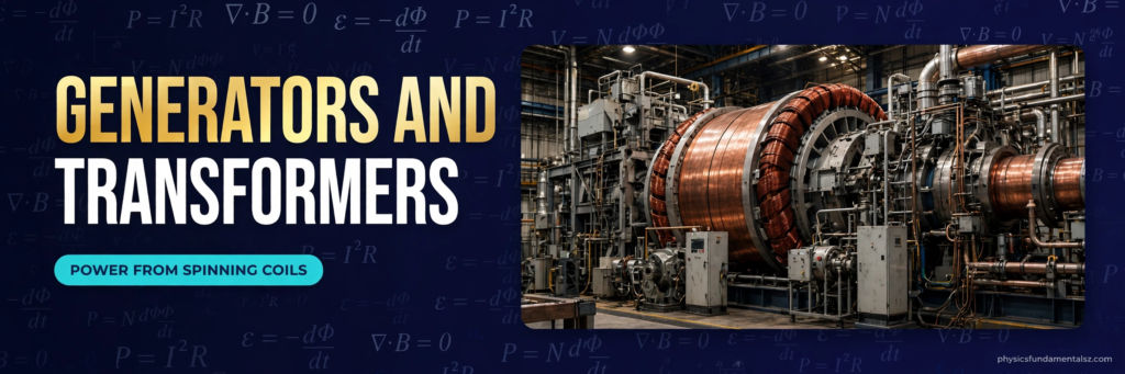
Almost every watt of grid electricity comes from electromagnetic induction. Coal, gas, nuclear, hydroelectric, and wind power plants all do the same thing at the final step: spin a coil (or a magnet) inside a magnetic field. The energy source differs — steam, falling water, wind — but the physics of the generator is identical.
Induction Cooktops
An induction hob contains a coil carrying high-frequency alternating current. The changing magnetic field induces eddy currents in the metal base of the pan, and the pan’s own electrical resistance turns those currents into heat. The hob surface itself stays comparatively cool, because the heat is generated in the pan, not in the hob. This is also why induction hobs only work with ferromagnetic pans: the magnetic properties of the pan concentrate the field and strengthen the effect.
Wireless Charging
Your phone’s wireless charger contains a transmitter coil. When you place your phone on it, the alternating current in the transmitter coil creates a changing magnetic field, which induces a current in a receiver coil inside the phone. That current charges the battery. The same principle, scaled up, is being tested for charging electric vehicles parked over pads embedded in the ground.
Metal Detectors and Security Scanners
A metal detector’s search coil produces a changing magnetic field. When it passes over a metal object, eddy currents are induced in the object, and those currents create their own magnetic field, which the detector senses. Airport scanners and food-industry metal detectors use the same idea to find hidden or contaminating metal.
Magnetic Braking and Eddy Current Brakes
Some trains and roller coasters use eddy current brakes: magnets move past a metal rail or disc, inducing eddy currents that oppose the motion through Lenz’s law. The braking force is smooth, contact-free, and never wears out, because nothing touches. It is Lenz’s law working as a brake pedal.
Guitar Pickups and Microphones
An electric guitar pickup is a small coil wrapped around a magnet, placed under the strings. When a steel string vibrates, it disturbs the magnetic field, changing the flux through the coil and inducing a tiny current that mirrors the vibration. That signal becomes the guitar’s sound. Dynamic microphones work the same way: sound waves move a coil in a magnetic field, and induction converts the motion into an electrical signal.
Eddy Currents: Useful and Wasteful at the Same Time
Eddy currents are loops of current induced inside a solid piece of metal when the magnetic flux through it changes. They are the same phenomenon as induction in a coil, except the “circuit” is the bulk metal itself.
Eddy currents are useful in induction cooking, metal detectors, and magnetic braking. But in transformers and motors, they are a problem: they waste energy as heat in the iron core, warming the transformer for no benefit.
Engineers fight eddy currents by laminating transformer cores — building them from thin insulated sheets of iron instead of one solid block. The thin sheets break up the paths eddy currents can take, so the currents stay small and the wasted heat drops dramatically. If you have ever noticed the thin layers in a transformer core, that is why they are there.
Common Mistakes Students Make
Mistake 1: Thinking a Strong Field Alone Creates Current
A strong magnetic field sitting still next to a coil does nothing. It is the change in flux that matters, not the size of the field. A weak field changing quickly can induce a bigger EMF than a strong field changing slowly.
Mistake 2: Forgetting the Number of Turns
Faraday’s law multiplies by N. Students often calculate the EMF for one loop and forget to multiply by the number of turns in the coil. Always check whether the question gives you N, and always use it.
Mistake 3: Confusing Flux With Flux Change
Flux (Φ) and rate of change of flux (ΔΦ/Δt) are different quantities. A coil can have maximum flux and zero EMF at the same instant — this happens in a generator when the coil is perpendicular to the field. EMF depends on how fast flux is changing, not on how much flux there is.
Mistake 4: Getting Lenz’s Law Backwards
The induced current opposes the change, not the field itself. If flux is increasing, the induced field fights the increase. If flux is decreasing, the induced field tries to maintain it. Saying “the induced current always opposes the magnetic field” is wrong — it opposes the change in flux.
Mistake 5: Using the Wrong Angle in Φ = BA cos θ
Theta is the angle between the field and the normal to the loop, not the angle between the field and the plane of the loop. When the field is perpendicular to the loop’s surface, θ = 0° and flux is maximum. When the field lies in the plane of the loop, θ = 90° and flux is zero. Drawing the normal line on your diagram first prevents this error.
Electromagnetic Induction vs Electromagnetic Waves
These two ideas sound similar and are easy to confuse. Electromagnetic induction is a local effect: a changing magnetic field creates an electric field in a nearby conductor. Electromagnetic waves, like light and radio, are self-propagating disturbances of electric and magnetic fields travelling through space.
The connection is real — Maxwell’s equations unify them — but the phenomena are different. Induction needs a conductor and a changing flux. A light wave needs neither: it travels through empty space. If you understand that induction is about flux through a loop, and waves are about fields propagating, you will not mix them up.
For background on how waves themselves behave, our explainer on the difference between transverse and longitudinal waves covers the wave side of the story.
The History in Brief: Faraday, Henry, and Maxwell
Michael Faraday demonstrated induction in August 1831 with a simple experiment: he wrapped two coils around an iron ring and noticed a brief current in the second coil whenever he connected or disconnected the battery on the first. The current appeared only at the moment of change — exactly as his law would later state.
Joseph Henry, working independently in the United States, observed the same effect and went on to build powerful electromagnets. The unit of inductance, the henry, is named after him.
James Clerk Maxwell then took Faraday’s experimental results and expressed them in mathematical form. One of Maxwell’s four equations is Faraday’s law in its full form, and those equations predicted electromagnetic waves — which Heinrich Hertz confirmed experimentally in 1887. Induction, discovered on a workbench, led within fifty years to radio.
You can read Faraday’s original account and the modern statement of his law in the excellent summaries at Khan Academy and the HyperPhysics reference pages, and the Britannica entry on Faraday’s law gives the historical context.
Self-Induction: When a Coil Induces EMF in Itself
So far we have looked at induction caused by an external magnet or a separate coil. But a coil can also induce an EMF in itself, and this effect — called self-induction — matters in almost every real circuit.
When the current through a coil changes, the magnetic field the coil itself produces also changes. That changing flux links the coil’s own turns, so an EMF is induced in the very coil carrying the current. By Lenz’s law, this self-induced EMF opposes the change in current: it fights a rising current and tries to sustain a falling one.
The size of the effect is given by the coil’s inductance, symbol L, measured in henries (H). A coil with high inductance resists changes in current strongly; a coil with low inductance barely notices. The self-induced EMF follows a simple formula: ε = −L ΔI / Δt, where ΔI/Δt is the rate of change of current.
Self-induction is why fluorescent tube ballasts and car ignition coils work. In a car ignition coil, interrupting the current suddenly produces a huge rate of change, and the self-induced EMF spikes to thousands of volts — enough to fire a spark plug. It is also why switching off a large electromagnet can produce a surprising spark across the switch contacts: the collapsing field drives a brief, high-voltage pulse.
Engineers also use inductors deliberately as circuit components. In power supplies, inductors smooth out ripples in current. In radio tuners, an inductor paired with a capacitor selects one frequency and rejects others. In all these cases, the same Faraday’s law applies — only the source of the changing flux is the coil itself rather than a moving magnet.
Frequently Asked Questions
1. What is electromagnetic induction in simple words?
It is the creation of electricity in a wire when a nearby magnetic field changes. Move a magnet near a coil, and a current flows — no battery needed.
2. Who discovered electromagnetic induction?
Michael Faraday discovered it in 1831, with Joseph Henry independently observing the same effect in the same year.
3. What is Faraday’s law of electromagnetic induction?
Faraday’s law states that the induced EMF in a circuit equals the negative rate of change of magnetic flux through it, multiplied by the number of turns: ε = −N(ΔΦ/Δt).
4. What is Lenz’s law?
Lenz’s law states that the direction of the induced current always opposes the change in magnetic flux that produced it. It is a consequence of the conservation of energy.
5. What is magnetic flux?
Magnetic flux is the amount of magnetic field passing through an area, calculated as Φ = BA cos θ, and measured in webers.
6. Does electromagnetic induction work with a stationary magnet?
No. A stationary magnet creates a steady field, so the flux does not change and no EMF is induced. Something must move or vary.
7. Why do generators produce alternating current?
Because the coil rotates, the flux through it rises and falls sinusoidally, so the induced EMF alternates in direction with each half-turn.
8. Can a transformer work with direct current?
No. DC produces a steady magnetic field, so there is no changing flux in the secondary coil and no induced EMF (apart from a brief pulse when the current is switched on or off).
9. What are eddy currents?
Eddy currents are loops of electric current induced inside bulk metal when the magnetic flux through it changes. They are useful in induction cooking and magnetic braking, but wasteful as heat in transformer cores.
10. How does wireless charging use electromagnetic induction?
A transmitter coil carrying alternating current creates a changing magnetic field, which induces a current in a receiver coil in the phone. That induced current charges the battery.
11. Why does increasing the number of coil turns increase the EMF?
Each turn experiences the same flux change, and each contributes its own EMF. The total EMF is the sum across all turns, so it scales directly with N.
12. What is the difference between induced EMF and induced current?
Induced EMF is the voltage created by the changing flux. Induced current is the flow of charge that results when that voltage is applied to a closed circuit. EMF can exist in an open coil with no current flowing.
13. How is electromagnetic induction used in power stations?
Turbines spin coils (or magnets) inside magnetic fields, and induction converts that rotational motion into the alternating current that feeds the grid.
14. Why are transformer cores laminated?
Lamination breaks up the paths for eddy currents in the iron core, reducing wasted heat and making the transformer far more efficient.
15. Is electromagnetic induction dangerous?
The phenomenon itself is not dangerous, but the high voltages it produces in generators and transformers are. That is why power equipment is insulated, earthed, and kept behind barriers.
Key Takeaways
- Electromagnetic induction is the creation of an EMF when magnetic flux through a conductor changes.
- Faraday’s law, ε = −N(ΔΦ/Δt), gives the size of the EMF; Lenz’s law gives its direction.
- Flux can change through field strength, area, or angle — generators use rotation, transformers use a changing field.
- Induction powers generators, transformers, induction cooktops, wireless chargers, metal detectors, and magnetic brakes.
- The common exam traps are forgetting the number of turns, confusing flux with flux change, and getting Lenz’s law backwards.
Conclusion
Electromagnetic induction is a rare thing in physics: a single idea, discovered with a magnet and a coil of wire, that now powers the entire modern world. Every time you switch on a light, charge a phone wirelessly, or cook on an induction hob, you are using Faraday’s discovery.
If you are studying for AP Physics or any electromagnetism exam, master three things and the rest follows: the flux formula Φ = BA cos θ, Faraday’s law ε = −N(ΔΦ/Δt), and Lenz’s law’s rule that the induced current opposes the change. With those three, you can explain generators, transformers, and every worked example in this guide.
For more on the wave phenomena that induction relates to, read our guide to what refraction of light is, and for the fluid-flow counterpart to changing fields, see Bernoulli’s principle explained.