Why Do Capacitors Block DC but Pass AC? Explained Simply 2026
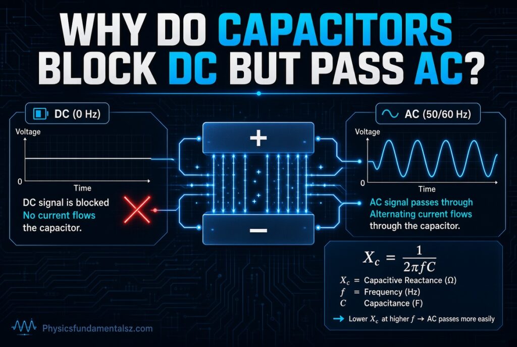
Why do capacitors block DC but pass AC? Because a capacitor has an insulating gap between its two plates, so steady direct current can never cross it.
Alternating current keeps reversing, so the plates charge and discharge again and again, and a current appears in the circuit even though no electrons cross the gap.
This single behavior sits behind audio amplifiers, power supplies, radio receivers, noise filters, and almost every circuit board you have ever held. Once you see why it happens, many parts of electronics start to make sense.
Table of Contents
Why Capacitors Block DC but Pass AC
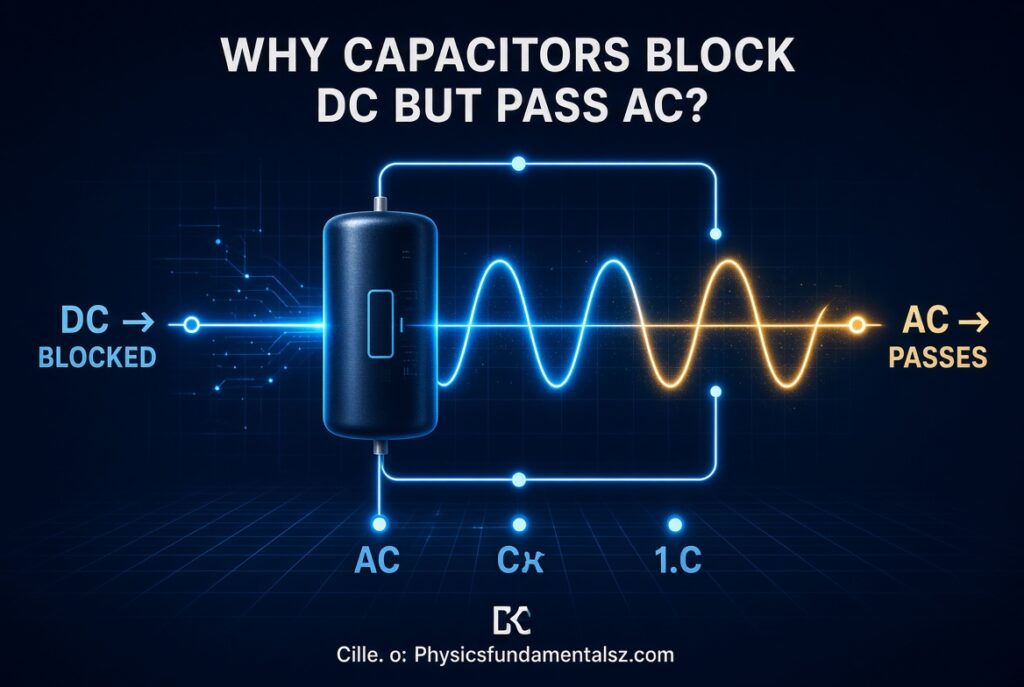
A capacitor blocks DC because its plates are separated by an insulator (the dielectric). Once the capacitor charges to the source voltage, current stops and the capacitor acts like an open circuit.
A capacitor passes AC because the changing voltage forces it to charge and discharge continuously. This repeated motion of charge in the outside circuit looks like current flowing “through” the capacitor.
In formula terms, capacitive reactance is Xc = 1 / (2πfC). At DC the frequency is zero, so reactance is infinite and current is blocked. At higher frequencies the reactance drops, so more current flows.
Key Takeaways
- A capacitor is two conductors separated by an insulator.
- DC current only flows while the capacitor is charging, then it stops.
- AC keeps the capacitor charging and discharging, so current keeps flowing in the wires.
- Capacitive reactance falls as frequency or capacitance rises.
- No electrons physically cross the dielectric in an ideal capacitor.
- This behavior is used in coupling, bypassing, decoupling, and filtering.
What Is a Capacitor?
A capacitor is a passive electronic component that stores energy in an electric field. Along with resistors and inductors, it is one of the three basic passive components in electronics.
It does not generate energy. It collects charge on its plates and gives it back when the circuit needs it.
Basic Structure of a Capacitor
Every capacitor has two conductive plates and a dielectric between them. The plates are usually metal foil or metal film. The dielectric can be air, ceramic, plastic film, paper, or a thin oxide layer.
Each plate has a lead that connects to the circuit. The two plates never touch each other.
To save space, many capacitors roll long sheets of foil and dielectric into a small cylinder. It looks compact, but electrically it is still two large plates separated by a gap.
Capacitance and the Farad
Capacitance measures how much charge a capacitor stores for each volt applied. The unit is the farad (F), named after Michael Faraday.
One farad equals one coulomb of charge per volt. Most real capacitors are far smaller, so you will see picofarads (pF), nanofarads (nF), and microfarads (µF).
The basic relationship is Q = C × V. Here Q is the stored charge in coulombs, C is capacitance in farads, and V is voltage in volts.
Capacitance Formula for Parallel Plates
For two parallel plates, capacitance is C = ε₀ × εr × A / d. Here ε₀ is the permittivity of free space (about 8.854 × 10⁻¹² F/m), εr is the relative permittivity of the dielectric, A is plate area, and d is the gap.
Bigger plates raise capacitance. A thinner gap raises capacitance. A dielectric with higher permittivity raises capacitance.
This is why a capacitor can be physically small and still hold a large capacitance. Engineers stack, roll, and etch the plates to pack in more area.
How a Capacitor Stores Energy
When voltage is applied, charge builds up on the plates and an electric field forms in the dielectric. The stored energy is E = ½ × C × V².
That energy is held in the field, not in the plates alone. When the circuit allows it, the capacitor releases the energy back as current.
This storing and releasing is the root of everything a capacitor does with AC and DC.
Why Does a Capacitor Block DC?
A capacitor blocks DC because the dielectric is an insulator. Direct current needs a continuous conducting path, and the gap between the plates breaks that path.
Still, the word “block” needs care. A capacitor does allow a short burst of current while it charges. After that, it blocks.
What Happens When a Capacitor Is Connected to a DC Source
Imagine an uncharged capacitor connected to a battery. The battery pushes electrons onto one plate and pulls electrons off the other.
The plate that gains electrons becomes negative. The plate that loses electrons becomes positive. An electric field now exists across the dielectric.
For a brief moment, current flows in the wires. This is the charging current.
Why the Charging Current Falls to Zero
As charge builds up, the voltage across the capacitor rises. This voltage opposes the battery voltage.
The difference between the battery voltage and the capacitor voltage keeps shrinking. Since current depends on that difference, the current keeps shrinking too.
When the capacitor voltage equals the source voltage, the difference is zero. Current stops completely.
The Capacitor as an Open Circuit in Steady State
In steady-state DC, a fully charged capacitor behaves like an open circuit. There is voltage across it, but no current through it.
This is what people mean when they say a capacitor “blocks DC”. The block is not instant, and it is not forever. It appears once the charging is finished.
If you disconnect the source, the capacitor can stay charged for a while. That stored charge is why large capacitors can still shock you after the power is off.
The Dielectric Is an Insulator
The charges on the two plates attract each other strongly. Yet they cannot cross, because the dielectric has almost no free electrons to carry current.
The electrons are held tightly to their atoms. They can shift slightly, which is called polarization, but they do not travel through.
If the voltage becomes too high, the dielectric can break down and conduct. That damages the capacitor, so every capacitor has a voltage rating.
Charging Equations and the RC Time Constant
In a circuit with a resistor R and capacitor C, charging follows an exponential curve. The capacitor voltage is Vc(t) = Vs × (1 − e^(−t/RC)).
The charging current is i(t) = (Vs / R) × e^(−t/RC). It starts at its largest value and decays toward zero.
The product RC is called the time constant, written τ (tau). It tells you how fast the capacitor charges.
| Time | Capacitor Voltage (% of Source) | Charging Current (% of Maximum) |
|---|---|---|
| 1τ | 63.2% | 36.8% |
| 2τ | 86.5% | 13.5% |
| 3τ | 95.0% | 5.0% |
| 4τ | 98.2% | 1.8% |
| 5τ | 99.3% | 0.7% |
After about five time constants, the capacitor is considered fully charged. At that point DC current is effectively zero.
Why Does a Capacitor Pass AC?
A capacitor passes AC because the source voltage never stays still. It rises, falls, reverses, and repeats, so the capacitor never reaches a final steady state.
Each change in voltage makes charge move onto or off the plates. That movement of charge is current in the external circuit.
Continuous Charging and Discharging
During the first part of an AC cycle, voltage rises and the capacitor charges. Charge flows in through one lead and out through the other.
As the voltage peaks and starts to fall, the capacitor discharges. Current flows the opposite way.
When the source polarity reverses, the capacitor charges in the opposite direction. This cycle repeats 50 or 60 times a second on mains power, and millions of times a second in radio circuits.
The Current Equation: i = C × dv/dt
The current through a capacitor depends on how fast the voltage changes. The equation is i = C × (dv/dt).
If voltage is constant, dv/dt is zero, so current is zero. That is the DC case.
If voltage changes quickly, dv/dt is large, so current is large. That is why fast AC signals pass easily.
Current Leads Voltage by 90 Degrees
For a sine wave, current through an ideal capacitor reaches its peak a quarter cycle before voltage does. Engineers say current leads voltage by 90°.
This happens because current follows the rate of change of voltage. The rate of change is highest when the sine wave crosses zero.
The phase shift is also why an ideal capacitor does not consume real power in an AC circuit. It stores energy and returns it every cycle.
A Step-by-Step Look at One AC Cycle
- Voltage starts at zero and rises. The capacitor charges and current is at its maximum.
- Voltage reaches its positive peak. The capacitor is fully charged for that instant and current is zero.
- Voltage falls toward zero. The capacitor discharges and current reverses.
- Voltage swings negative. The capacitor charges with opposite polarity.
- Voltage reaches its negative peak. Current is zero again.
- Voltage returns toward zero. The capacitor discharges and the cycle repeats.
At no point do electrons jump the gap. The circuit simply sees current moving in and out of the plates.
Does Current Really Flow Through a Capacitor?
Strictly speaking, no. In an ideal capacitor, no electrons cross the dielectric. What flows is conduction current in the wires and a different kind of current inside the gap.
This is the part many beginner explanations skip. It also explains why the “passes AC” idea is a useful shortcut and not a literal description.
Maxwell’s Displacement Current
James Clerk Maxwell introduced displacement current to complete the laws of electromagnetism. It is not moving charge. It is the effect of a changing electric field.
When the electric field in the dielectric changes, it acts like a current for the magnetic field. This keeps the current in the circuit continuous, with no break at the gap.
So in the wires you have conduction current. Between the plates you have displacement current. Together they form an unbroken loop.
Conduction Current vs Displacement Current
| Feature | Conduction Current | Displacement Current |
|---|---|---|
| Cause | Movement of free charges | Changing electric field |
| Where it occurs | Wires, plates, conductors | Dielectric between plates |
| Needs moving electrons | Yes | No |
| Present in steady DC across a capacitor | Only during charging | No (field is constant) |
| Present in AC | Yes, in the wires | Yes, in the dielectric |
With DC, the field becomes constant once charging ends. A constant field produces no displacement current, so the loop is broken.
With AC, the field keeps changing. Displacement current exists all the time, so the loop stays complete.
Capacitive Reactance Explained
Capacitive reactance is the opposition a capacitor offers to AC. It is measured in ohms, just like resistance, but it depends on frequency.
Reactance is the cleanest mathematical answer to why capacitors block DC but pass AC.
The Capacitive Reactance Formula
The formula is Xc = 1 / (2π × f × C). Here f is frequency in hertz and C is capacitance in farads.
You can also write it as Xc = 1 / (ω × C), where ω = 2πf is the angular frequency in radians per second.
Higher frequency means lower reactance. Higher capacitance also means lower reactance.
Why Reactance Is Infinite at DC
DC has a frequency of zero. Put f = 0 into the formula and the denominator becomes zero.
Dividing by zero gives infinity. In physical terms, the capacitor offers infinite opposition to steady current.
That is the mathematical version of an open circuit.
Why Reactance Falls as Frequency Rises
At higher frequency the voltage changes faster. Faster change means a bigger dv/dt, and a bigger dv/dt means more current for the same capacitance.
More current at the same voltage means lower opposition. So reactance falls.
At very high frequencies, a capacitor can behave almost like a short circuit. This is why capacitors are used to shunt high-frequency noise to ground.
Capacitive Reactance Examples
| Capacitance | 50 Hz | 60 Hz | 1 kHz | 100 kHz |
|---|---|---|---|---|
| 100 nF | 31,831 Ω | 26,526 Ω | 1,592 Ω | 15.9 Ω |
| 1 µF | 3,183 Ω | 2,653 Ω | 159 Ω | 1.59 Ω |
| 10 µF | 318 Ω | 265 Ω | 15.9 Ω | 0.159 Ω |
| 100 µF | 31.8 Ω | 26.5 Ω | 1.59 Ω | 0.0159 Ω |
Look at the 10 µF row. At 60 Hz it offers about 265 ohms. At 100 kHz it offers about 0.16 ohms.
Same capacitor, very different behavior. The only change is frequency.
Capacitor Impedance in Complex Form
In AC analysis, engineers write capacitor impedance as Z = 1 / (jωC), which equals −j / (ωC). The “j” marks the 90° phase shift.
The negative sign shows that the voltage lags the current. Resistors have no phase shift, and inductors have the opposite sign.
This notation lets you handle capacitors in circuits with resistors and inductors using ordinary algebra.
How Frequency Controls What a Capacitor Passes
A capacitor acts like a frequency-dependent gate. Low frequencies meet high reactance and struggle to pass. High frequencies meet low reactance and pass easily.
DC sits at the extreme low end. It is the slowest “signal” possible, so it is blocked completely after charging.
This is the reason a single capacitor can separate a slow DC level from a fast audio or radio signal riding on top of it.
A Quick Mental Model
Think of the capacitor as a very picky door. Slow changes get the door slammed shut. Fast changes find it wide open.
The faster the signal wiggles, the less the capacitor resists. The slower it wiggles, the more it resists.
Capacitor in a DC Circuit vs Capacitor in an AC Circuit
| Behavior | DC Circuit | AC Circuit |
|---|---|---|
| Current after startup | Zero | Continuous |
| Voltage across capacitor | Constant at source voltage | Changes with the source |
| Reactance | Infinite (f = 0) | Finite, equals 1/(2πfC) |
| Acts like | Open circuit | Frequency-dependent impedance |
| Energy | Stored, no further exchange | Stored and returned every cycle |
| Phase relationship | Not applicable | Current leads voltage by 90° |
| Typical role | Storage, smoothing, blocking | Coupling, filtering, tuning |
A Water Pipe Analogy
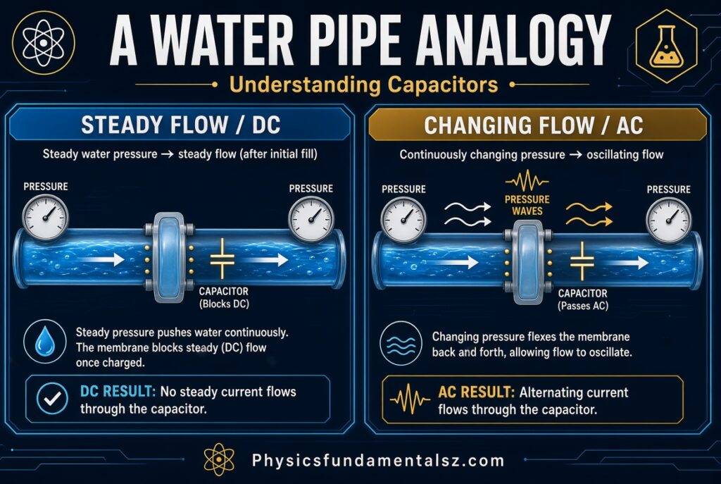
Picture a water pipe with a flexible rubber sheet stretched across the middle. Water cannot pass through the sheet, but the sheet can stretch.
Push water in from one side with steady pressure. The sheet stretches, a little water moves, then the sheet is taut and flow stops. That is DC.
Now push and pull the water back and forth quickly. The sheet flexes both ways, and water moves in and out on both sides. It looks like water flows through, but none actually crosses. That is AC.
Bigger sheet, more stretch, more water movement. That matches larger capacitance.
Real Capacitors Are Not Ideal
Everything above describes an ideal capacitor. Real parts have small flaws that matter in design, especially at high frequency or in precision circuits.
Knowing these flaws helps you explain why a real capacitor does not block DC perfectly and does not pass AC perfectly.
Leakage Current
No dielectric is a perfect insulator. A tiny leakage current flows through it, even with DC.
In a ceramic or film capacitor, leakage is extremely small. In an aluminum electrolytic capacitor, it is higher and depends on voltage, temperature, and age.
This is why a real capacitor does not hold its charge forever. It slowly discharges through its own leakage.
Equivalent Series Resistance (ESR)
ESR is the small resistance of the leads, plates, and dielectric losses combined. It acts like a resistor in series with the ideal capacitor.
ESR causes heating when AC current flows. In power supplies with large ripple current, low-ESR capacitors are chosen to avoid overheating.
Equivalent Series Inductance (ESL)
The leads and internal structure also add a small inductance. At low frequency it does not matter.
At high frequency, this inductance grows in importance and can dominate the behavior. That is why a “capacitor” can start acting like an inductor at very high frequencies.
Self-Resonant Frequency
Every real capacitor has a self-resonant frequency, where its capacitive reactance and its ESL reactance cancel. Below that point it behaves like a capacitor. Above it, it behaves like an inductor.
This is why designers place a small ceramic capacitor next to a large one. Each covers a different frequency range.
Capacitors Do Not Block DC Instantly
The statement “a capacitor blocks DC” is true only after charging completes. At the moment you connect a DC source, the capacitor passes a surge of current.
This transient behavior is useful on its own. It creates delays, pulses, and timing signals.
Inrush Current
An uncharged capacitor acts like a short circuit at the instant of connection. Current is limited only by the source and the series resistance.
In power supplies, this can cause a large inrush current. Designers add resistors or thermistors to limit it.
Why a Capacitor Looks Like a Wire to a Sudden Change
A sudden voltage step is a very fast change, so it contains high-frequency content. The capacitor passes that step as a pulse of current.
This is the reason a capacitor “passes” the edges of a square wave but blocks its flat parts. It is also the reason capacitive coupling can pass digital edges.
Polarized vs Non-Polarized Capacitors
Some beginner articles claim only non-polarized capacitors pass AC. The better way to put it is that polarized capacitors are designed for DC bias and can be damaged by reverse voltage.
A polarized capacitor, such as an aluminum electrolytic or tantalum capacitor, has a positive and a negative lead. The oxide layer works correctly only when the voltage polarity is right.
Can You Use an Electrolytic Capacitor with AC?
A standard polarized electrolytic capacitor should not be connected across a pure AC supply. Reverse voltage can damage the oxide layer, cause heating, and even make it vent or burst.
If AC must pass through an electrolytic position, use a bipolar (non-polarized) electrolytic capacitor. Or place two polarized capacitors back to back.
Can You Use an AC Capacitor in a DC Circuit?
Yes, if the voltage rating and the capacitor type are suitable. A film capacitor rated for AC will also work in a DC circuit, since a DC rating is usually higher than an AC rating for the same part.
The reverse is not always true. A DC-rated capacitor may fail under continuous AC voltage because of heating and the repeated stress on the dielectric.
Always read the datasheet. Look for the rated DC voltage, rated AC voltage, and ripple current rating.
Capacitor Types and How They Handle AC and DC
| Capacitor Type | Dielectric | Polarity | Typical Use | AC Handling |
|---|---|---|---|---|
| Ceramic (MLCC) | Ceramic | Non-polarized | Decoupling, bypassing, RF | Excellent at high frequency |
| Film (polyester, polypropylene) | Plastic film | Non-polarized | Coupling, audio, motor run, filters | Excellent, low loss |
| Aluminum electrolytic | Aluminum oxide | Polarized | Bulk storage, power supply smoothing | Limited, needs DC bias |
| Tantalum | Tantalum pentoxide | Polarized | Compact decoupling, low-leakage storage | Limited, needs DC bias |
| Supercapacitor | Electric double layer | Polarized | Energy backup, short bursts | Not intended for AC signals |
| Mica / Silver mica | Mica | Non-polarized | Precision RF, oscillators | Excellent, stable |
| Air-gap / Variable | Air | Non-polarized | Tuning in radios | Excellent |
Ceramic and film capacitors are the common choice for signal paths. Electrolytics are chosen when large capacitance is more important than precision.
The Coupling Capacitor: A DC Blocking Capacitor
A coupling capacitor sits in series with a signal path. It lets the AC signal go through and stops the DC level.
This is the most direct everyday use of the “blocks DC, passes AC” property. It is also called a DC blocking capacitor.
Why Amplifiers Need Coupling Capacitors
Each amplifier stage sets its own DC bias voltage so the transistor works in the right region. If you connect two stages directly, the DC level from one would disturb the bias of the next.
A coupling capacitor between them passes the audio or radio signal but blocks the DC bias. Each stage keeps its own operating point.
Coupling in Audio Equipment
Audio jacks, guitar pedals, microphone inputs, and headphone outputs often use coupling capacitors. They remove DC offset that could damage speakers or add noise.
A DC offset on a speaker line can heat the voice coil. A series capacitor keeps it out.
Choosing a Coupling Capacitor Value
The capacitor and the input resistance of the next stage form a high-pass filter. The cutoff frequency is fc = 1 / (2π × R × C).
You want fc well below the lowest frequency you care about. For audio, that means below about 20 Hz.
| Input Resistance | Coupling Capacitor | Cutoff Frequency |
|---|---|---|
| 10 kΩ | 1 µF | 15.9 Hz |
| 10 kΩ | 10 µF | 1.59 Hz |
| 100 kΩ | 1 µF | 1.59 Hz |
| 100 kΩ | 100 nF | 15.9 Hz |
| 1 kΩ | 100 µF | 1.59 Hz |
If the capacitor is too small, bass frequencies get weakened. If it is very large, it costs more and takes more space, with little gain.
The Bypass Capacitor
A bypass capacitor gives unwanted AC a shortcut to ground. It is wired from a point in the circuit to ground.
The DC at that point is blocked by the capacitor, so the bias is not disturbed. The AC noise sees low reactance and drains away.
Where Bypass Capacitors Are Used
You see bypass capacitors across emitter resistors in transistor amplifiers, across power rails, and across sensor lines. They keep the DC operating point stable while letting the signal or noise path stay clean.
In a common-emitter amplifier, an emitter bypass capacitor boosts AC gain without upsetting DC bias. This is a classic textbook circuit.
The Decoupling Capacitor
A decoupling capacitor sits close to the power pins of an integrated circuit. It supplies quick bursts of current when the chip switches, and it keeps the supply voltage steady.
It also keeps fast switching noise from spreading to other parts of the board.
Why Digital Chips Need Decoupling
Microcontrollers and processors draw current in sharp pulses. The power wiring has inductance, so it cannot supply these pulses fast enough on its own.
A nearby capacitor acts as a tiny local reservoir. A typical choice is a 100 nF ceramic capacitor on each supply pin, often with a larger capacitor nearby for slower changes.
Decoupling Placement Tips
- Place the capacitor as close to the IC power pin as possible.
- Keep the loop between the capacitor, the power pin, and ground short.
- Use a low-ESL package such as a small surface-mount ceramic capacitor.
- Combine different values to cover a wider frequency range.
Capacitors in Filters: High-Pass and Low-Pass
Because reactance depends on frequency, a capacitor and a resistor can sort signals by frequency. This is the basis of filters.
These filters are direct proof of the “blocks low frequency, passes high frequency” rule.
RC High-Pass Filter
In a high-pass filter, the capacitor is in series with the signal and the resistor goes to ground. Low frequencies face high reactance and are blocked. High frequencies pass.
DC is the lowest frequency of all, so it is blocked completely. This is the same circuit used for AC coupling.
RC Low-Pass Filter
In a low-pass filter, the resistor is in series and the capacitor goes to ground. High frequencies are shunted to ground through the capacitor. Low frequencies and DC continue forward.
Here the capacitor passes high-frequency AC to ground, which is exactly why the output loses those frequencies.
Cutoff Frequency Examples
| Resistor | Capacitor | Cutoff Frequency |
|---|---|---|
| 1 kΩ | 100 nF | 1,592 Hz |
| 10 kΩ | 100 nF | 159 Hz |
| 10 kΩ | 10 nF | 1,592 Hz |
| 100 kΩ | 1 nF | 1,592 Hz |
| 1 kΩ | 1 µF | 159 Hz |
At the cutoff frequency, the output drops to about 70.7% of the input voltage, which is −3 dB.
Band-Pass and LC Filters
Add an inductor and you can build band-pass and notch filters. Inductors do the opposite of capacitors: they pass DC and block high frequency.
Together, a capacitor and an inductor can select a narrow band. This is how a radio tunes to one station and rejects the rest.
Power Supply Smoothing and Ripple Reduction
After rectification, mains AC becomes pulsating DC. It has a large DC part and a ripple riding on top.
A large filter capacitor across the output charges to the peak voltage and supplies the load between peaks. It passes the ripple (the AC part) around the load and keeps the DC level steady.
How Much Capacitance Is Needed?
A rough rule for a full-wave rectifier is C = I / (2 × f × Vripple). Here I is load current, f is mains frequency, and Vripple is the allowed ripple voltage.
For a 1 A load, 60 Hz mains, and 1 V of ripple, you need about 8,333 µF. That is why power supplies use large electrolytic capacitors.
Timing and Delay Circuits
The charging time of a capacitor can set a delay. A resistor and capacitor together produce a predictable time constant.
This is the basis of the 555 timer circuit, blinkers, power-on reset circuits, and simple debouncing for switches.
Example: Delay with an RC Circuit
With R = 100 kΩ and C = 10 µF, the time constant is 1 second. The capacitor reaches about 63% of the supply in 1 second, and about 99% in 5 seconds.
A comparator can watch this voltage and trigger an action at a chosen threshold.
Real-World Applications of the DC-Blocking, AC-Passing Property
| Application | What the Capacitor Does | Why It Works |
|---|---|---|
| Audio amplifier input | Blocks DC offset, passes sound | High reactance at DC, low at audio |
| Speaker crossover | Sends high frequencies to the tweeter | Reactance drops at high frequency |
| Power supply filter | Removes ripple | Passes AC ripple, holds DC level |
| Oscilloscope AC coupling | Hides DC offset to show small signals | Blocks DC, passes the waveform |
| Radio tuning circuit | Selects a frequency with an inductor | Reactance cancels at resonance |
| Motor run/start capacitor | Creates a phase shift for torque | Current leads voltage by 90° |
| Touchscreen sensing | Detects a finger by capacitance change | Uses AC excitation of electrodes |
| Digital IC decoupling | Supplies fast current bursts | Low reactance at high frequency |
| RF bias tee | Separates DC power from RF signal | Capacitor blocks DC, inductor blocks RF |
| Snubber circuit | Absorbs voltage spikes | Passes fast transients |
Capacitor vs Inductor: Opposite Behaviors
An inductor does the opposite of a capacitor. It passes DC and resists changes in current, so it opposes high-frequency AC.
Think of them as mirror images. One resists changes in voltage, the other resists changes in current.
| Feature | Capacitor | Inductor |
|---|---|---|
| Stores energy in | Electric field | Magnetic field |
| Behavior at DC (steady state) | Open circuit | Short circuit |
| Behavior at high frequency | Low impedance | High impedance |
| Reactance formula | Xc = 1 / (2πfC) | XL = 2πfL |
| Current vs voltage phase | Current leads by 90° | Current lags by 90° |
| Opposes changes in | Voltage | Current |
| Common role | Block DC, pass AC, filter | Pass DC, block AC, filter |
Common Misconceptions About Capacitors, DC, and AC
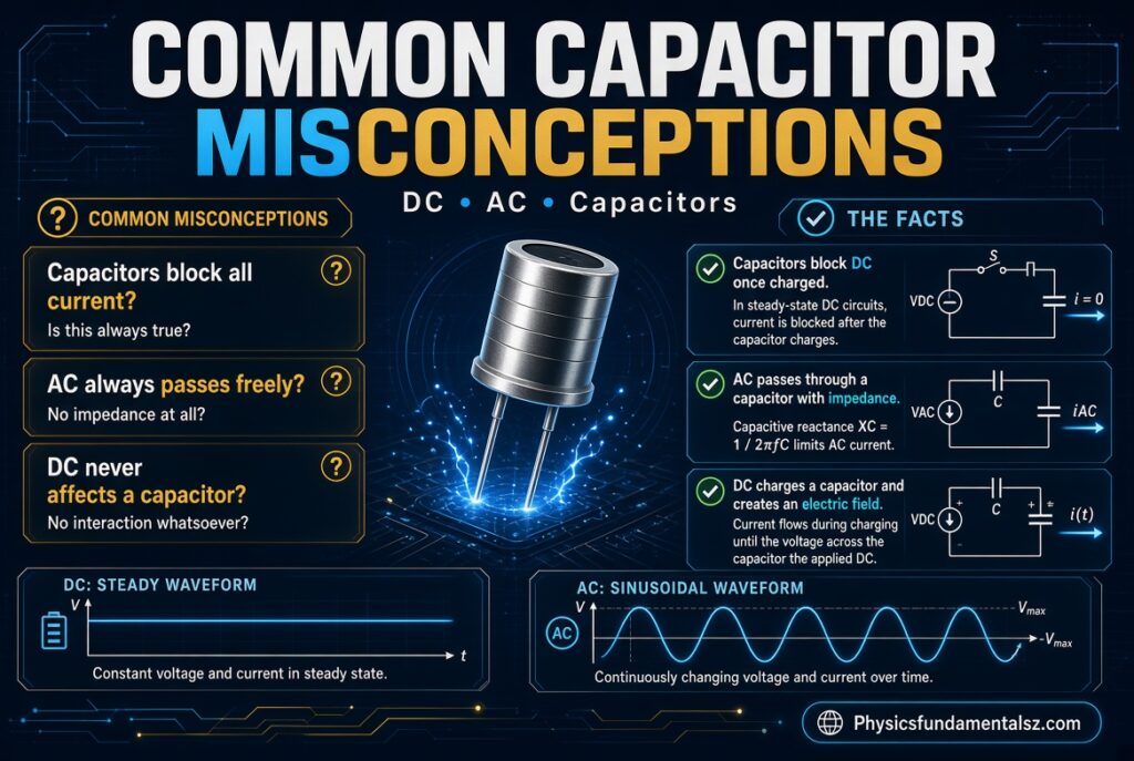
Misconception 1: Electrons Flow Through the Dielectric
In an ideal capacitor, they do not. Charge moves in the wires, and the electric field changes in the gap. The effect looks like current through the part.
Misconception 2: A Capacitor Blocks DC at All Times
It blocks DC only after it has charged. During the charging period, DC current flows.
Misconception 3: A Capacitor Is a Short Circuit for AC
It is a short circuit only in the limit of very high frequency or very large capacitance. For normal values, it has a measurable reactance that limits current.
Misconception 4: Bigger Capacitors Always Pass More Signal
Bigger capacitance lowers reactance, but real capacitors have ESR and ESL. At high frequency, a huge electrolytic can be worse than a small ceramic.
Misconception 5: Capacitors Cannot Pass DC Under Any Condition
A real capacitor has some leakage, so a tiny DC current exists. It is usually negligible in film and ceramic parts, but it can matter in precision circuits and with electrolytics.
Mistakes to Avoid When Using Capacitors in AC and DC Circuits
- Connecting a polarized electrolytic capacitor backward or across AC.
- Ignoring the voltage rating. Choose a rating with a safe margin above the working voltage.
- Using a DC-rated capacitor across mains AC without checking its AC rating.
- Forgetting ripple current limits in power supply filters.
- Placing decoupling capacitors far from the IC pins.
- Ignoring temperature effects, since some ceramic types lose capacitance with DC bias and heat.
- Touching large charged capacitors without discharging them first.
- Assuming a coupling capacitor value works without checking the cutoff frequency.
DC Bias Effect on Ceramic Capacitors
Some high-permittivity ceramic capacitors (such as X5R and Y5V types) lose a big part of their rated capacitance when a DC voltage is applied. A 10 µF part can behave like 3 µF under bias.
Check the manufacturer’s DC bias curves when choosing parts for decoupling and filtering.
Simple Experiments to See This Behavior Yourself
You do not need a lab to see the effect. A few common parts and a basic meter or oscilloscope are enough.
Experiment 1: Capacitor Charging with a Multimeter
Connect a resistor and capacitor in series to a 9 V battery. Measure the voltage across the capacitor. It rises and levels off at 9 V, and current drops to zero.
Use a large capacitor such as 1,000 µF with a 10 kΩ resistor to make the change slow enough to watch.
Experiment 2: LED Test with DC and AC
Connect an LED in series with a capacitor and a resistor, then to a DC source. The LED flashes briefly and goes dark.
Replace the DC source with a low-voltage AC source from a function generator. The LED stays lit (it may look dim), since current keeps flowing in the wires.
Experiment 3: Oscilloscope AC and DC Coupling
Feed a sine wave with a DC offset into an oscilloscope. In DC coupling, you see the wave sitting above zero. Switch to AC coupling and the wave centers on zero.
The scope has placed a capacitor in series with the input, which removes the DC part.
Experiment 4: Simulation in LTspice
Build an RC circuit and run a transient analysis with a DC source, then with a sine source. Plot the current in both cases.
You will see the DC current decay to zero, while the AC current continues with a 90° lead.
Worked Examples
Example 1: Reactance of a 10 µF Capacitor at 60 Hz
Xc = 1 / (2π × 60 × 10 × 10⁻⁶) = 1 / 0.003770 = about 265 Ω.
If you apply 12 V AC (RMS), the current is I = V / Xc = 12 / 265 = about 45 mA.
Example 2: Same Capacitor at DC
At f = 0, Xc approaches infinity. After charging, I = 0.
So the same 10 µF capacitor allows 45 mA at 60 Hz and none at DC.
Example 3: Cutoff of a Coupling Network
An amplifier input has 47 kΩ resistance. You use a 1 µF coupling capacitor.
fc = 1 / (2π × 47,000 × 1 × 10⁻⁶) = about 3.4 Hz. That is well below the audio range, so bass passes cleanly.
Example 4: Charge Stored in a 100 µF Capacitor at 12 V
Q = C × V = 100 × 10⁻⁶ × 12 = 1.2 × 10⁻³ coulombs, or 1.2 mC.
Energy E = ½ × C × V² = 0.5 × 100 × 10⁻⁶ × 144 = 7.2 mJ.
Safety Notes for Working With Capacitors
Large capacitors can hold dangerous charge after the power is off. This applies to power supplies, camera flash units, microwave ovens, and motor drives.
Always discharge them through a suitable resistor before touching the circuit. Never short a large capacitor directly with a screwdriver, since the sudden current can damage the part and cause burns.
Respect voltage ratings, observe polarity, and use proper enclosures for mains-connected circuits.
The Physics Behind It: Charge, Field, and Polarization
To understand the block-and-pass behavior at a deeper level, look at what happens inside the dielectric.
The dielectric does not carry current, but it is not passive. It responds to the electric field in a way that increases capacitance.
Dielectric Polarization
When an electric field is applied, the atoms or molecules in the dielectric stretch slightly. The positive parts shift one way and the negative parts shift the other.
This shift creates small internal dipoles that partly cancel the applied field. Because the field is reduced, more charge can be stored on the plates for the same voltage. That is how a dielectric raises capacitance.
Why Polarization Is Not Conduction
The charges in the dielectric move only a tiny distance and stay bound to their atoms. They do not travel from plate to plate.
With DC, the dielectric polarizes once and stays polarized. With AC, the polarization swings back and forth with the field. This back-and-forth motion of bound charge is a real contribution to displacement current.
Dielectric Loss and Heating
If the polarization cannot keep up with a very fast field, energy is lost as heat. This is called dielectric loss, and it is measured by the loss tangent (also called the dissipation factor, tan δ).
Low-loss materials such as polypropylene and C0G ceramic are preferred for high-frequency and high-precision work.
Dielectric Strength and Breakdown
Every dielectric can resist only so much electric field before it breaks down and conducts. Air breaks down at about 3 million volts per meter under standard conditions.
When breakdown happens inside a capacitor, it can short out the part. This is why the voltage rating matters, and why a DC-blocking capacitor is not a safe barrier for unlimited voltage.
Kirchhoff’s Current Law and the Capacitor
Kirchhoff’s current law says the current entering a node equals the current leaving it. At first glance, a capacitor seems to break this rule, because the gap has no conduction current.
The law holds once you count displacement current. The current into one plate equals the rate of change of charge on that plate, and the same amount leaves the other plate.
In circuit analysis, you simply treat the capacitor as a two-terminal element with i = C × dv/dt. The current into one lead always equals the current out of the other lead.
Superposition: A Signal With Both DC and AC Parts
Many real signals have a DC level and an AC part together. A common example is a sine wave riding on a 2.5 V offset.
Because the circuit is linear, you can treat the two parts separately and add the results. This idea is called superposition.
What the Capacitor Does to Each Part
For the DC part, the capacitor has infinite reactance and blocks it. For the AC part, it has finite reactance and passes it.
The output of a series capacitor is the AC part centered on zero, as long as the AC frequency is above the cutoff of the network.
Why This Matters for Sensors
Many sensors output a small AC signal on top of a large DC level. A coupling capacitor removes the DC level so an amplifier can boost only the tiny signal.
This works for microphones, vibration sensors, ECG and EEG front ends, and photodiode amplifiers.
Power in a Capacitor: Why It Does Not Heat Up Ideal Circuits
In an ideal capacitor, the average power over a full AC cycle is zero. Power flows into the capacitor for a quarter cycle, then flows back out for the next quarter.
This back-and-forth power is called reactive power, and it is measured in volt-amperes reactive (VAR).
Real Power vs Reactive Power
Real power does work, such as making heat or light. Reactive power only swings between the source and the capacitor.
A real capacitor also has ESR, so a small part of the current produces real power loss as heat.
Power Factor Correction
Motors and transformers behave like inductors and draw lagging current. A bank of capacitors, which draws leading current, can cancel part of that lag.
Factories use this technique to improve power factor and cut utility charges. It is another everyday use of the capacitor’s 90° phase behavior.
Capacitors in Series and Parallel
Real circuits often combine capacitors. The rules are opposite to those for resistors.
Capacitors in Parallel
Parallel capacitors add: C_total = C1 + C2 + C3. The plate area effectively increases, so the total capacitance increases.
Reactance falls, so more AC current flows for the same voltage.
Capacitors in Series
Series capacitors combine as 1/C_total = 1/C1 + 1/C2 + 1/C3. The total capacitance is smaller than the smallest one.
This is like making the gap thicker. Reactances add, so less AC current flows.
| Arrangement | Total Capacitance | Total Reactance | Typical Reason to Use |
|---|---|---|---|
| Parallel | Adds up | Decreases | More capacitance, lower ESR |
| Series | Smaller than any single part | Increases | Higher voltage rating, back-to-back polarity |
| Mixed ceramic values in parallel | Sum of values | Low across wide band | Wideband decoupling |
Back-to-Back Polarized Capacitors
To make a non-polarized capacitor from two electrolytics, connect them in series with the same polarity terminals facing each other. Each one protects the other from reverse voltage.
The total capacitance is half of one capacitor if both are equal. This trick is used in some audio crossover and motor circuits.
Square Waves and Digital Signals Through a Capacitor
A square wave is a mix of many sine waves at different frequencies. A capacitor treats each frequency component differently.
The flat tops of the wave contain mostly low-frequency content. The sharp edges contain high-frequency content.
What the Output Looks Like
A series coupling capacitor passes the edges as spikes and lets the flat parts decay toward zero. The output looks like a sagging square wave if the cutoff is slightly below the signal frequency.
With a very small capacitor, only brief spikes remain. This is the “differentiator” circuit, since the output is roughly proportional to the rate of change of the input.
Why Digital Designers Care
Fast digital edges produce high-frequency energy that travels through capacitive coupling between traces. This is called crosstalk, and it is another example of capacitors passing fast changes.
Careful routing, ground planes, and spacing reduce unwanted capacitance between signal lines.
Stray and Parasitic Capacitance: Capacitors You Did Not Plan
Any two conductors separated by an insulator form a capacitor. Wires, circuit board traces, and even your body can create small capacitances.
These parasitic capacitances are tiny, usually a few picofarads. At high frequency, they pass signals that you wanted to block.
Examples of Parasitic Capacitance
- Between two adjacent traces on a circuit board.
- Between a transformer’s primary and secondary windings.
- Between a cable’s inner conductor and its shield.
- Between a person’s hand and a touch sensor.
- Between an oscilloscope probe tip and ground.
Why It Matters
Parasitic capacitance can limit the bandwidth of amplifiers, cause hum pickup, and let high-frequency noise cross isolation barriers. Understanding that capacitors pass fast changes helps you predict and cure these problems.
Mains Capacitor Dropper and Safety Capacitors
Some very small power supplies use a capacitor in series with the mains to limit current. This is called a capacitive dropper. It relies on the reactance of the capacitor at 50 or 60 Hz to restrict current without wasting heat in a resistor.
These circuits connect directly to the mains and have no isolation. They are dangerous and should only be built by people with proper training and approved parts.
X and Y Safety Capacitors
Capacitors connected across or from the mains to chassis must be certified safety-rated types. X capacitors go across the line. Y capacitors go from line to ground.
They are made to fail safely and are used in EMI filters. They pass high-frequency noise while blocking 50/60 Hz mains current as much as possible.
Capacitors in Radio and RF Circuits
At radio frequencies, capacitors show their strength as high-frequency passers. Even a tiny capacitor can have very low reactance at hundreds of megahertz.
This is why RF designers use small capacitors as DC blocks in antenna and amplifier lines.
Bias Tee
A bias tee combines a DC supply with an RF signal on one cable. A capacitor blocks DC from the RF port, and an inductor blocks RF from the DC port.
It is used to power antenna amplifiers and radio modules through the same coax cable that carries the signal.
Resonant Tuning
A capacitor and an inductor in parallel or series form a resonant circuit. The resonant frequency is f = 1 / (2π√(LC)).
Changing the capacitance changes the frequency. Old radios used a variable capacitor to tune stations.
Supercapacitors and DC Behavior
Supercapacitors, also called ultracapacitors, store thousands of times more energy than normal capacitors. They have capacitances of farads or more.
They still block DC once charged. Their main role is energy storage, not signal coupling.
Where They Are Used
Supercapacitors back up memory chips, smooth power in regenerative braking, and deliver short bursts in power systems. They charge and discharge fast and survive many cycles.
Their voltage rating per cell is low, usually 2.5 to 3 V, so cells are stacked in series for higher voltage.
A Short History: Leyden Jar to Modern Capacitor
The first capacitor was the Leyden jar, invented in the 1740s. It was a glass jar lined with metal inside and out, and it stored static electricity.
Michael Faraday later studied capacitance and dielectrics, and the unit of capacitance bears his name. James Clerk Maxwell then added displacement current to the equations of electromagnetism.
Today, billions of capacitors are made each day. Multilayer ceramic capacitors alone can have hundreds of layers inside a package smaller than a grain of rice.
How to Choose a Capacitor for AC or DC Blocking
Selecting the right capacitor depends on the signal, voltage, frequency, and environment. A few questions guide the choice.
Step-by-Step Selection Guide
- Define the lowest frequency you must pass. Set the cutoff well below it.
- Calculate the capacitance using C = 1 / (2π × R × fc), where R is the load or input resistance.
- Choose a voltage rating at least 1.5 to 2 times the highest DC voltage across the capacitor.
- Pick a dielectric. Film or C0G ceramic for low distortion, X7R for general use, electrolytic for large values.
- Check polarity needs. Use non-polarized parts when the voltage can reverse.
- Review ESR, ripple current, and temperature range for power uses.
- Check physical size and mounting style.
Decision Matrix
| Goal | Recommended Type | Reason |
|---|---|---|
| Audio coupling, high quality | Polypropylene or polyester film | Low distortion, stable |
| General signal coupling | X7R ceramic or film | Small, low cost |
| Power supply bulk smoothing | Aluminum electrolytic | High capacitance per volume |
| Digital IC decoupling | X7R or X5R ceramic | Low ESL, small |
| RF DC block | C0G/NP0 ceramic or mica | Stable, low loss |
| Motor run | Film (metallized polypropylene) | AC rated, self-healing |
| Energy backup | Supercapacitor | Very high capacitance |
Self-Healing and Reliability Notes
Metallized film capacitors can “self-heal.” If a tiny defect in the dielectric breaks down, the thin metal layer around the spot vaporizes and isolates the fault. The capacitor keeps working with a tiny loss of capacitance.
Electrolytic capacitors age because the electrolyte dries out, especially when hot. A common rule says life doubles for every 10 °C drop in temperature.
For long-lived designs, derate voltage, keep parts cool, and choose quality brands from manufacturers such as TDK, Murata, KEMET, Vishay, Panasonic, and Nichicon.
Frequently Asked Questions (FAQs)
Why do capacitors block DC but pass AC?
A capacitor has an insulating gap between its plates, so steady DC cannot cross it. AC keeps changing direction, so the capacitor charges and discharges continuously and current flows in the circuit.
Do capacitors really block DC?
They block DC only after they are fully charged. During charging, a brief current flows, and then it falls to zero.
Does current actually flow through a capacitor?
No electrons cross the dielectric in an ideal capacitor. Charge moves in the wires, and a changing electric field between the plates acts as displacement current.
What is capacitive reactance?
It is the opposition a capacitor gives to AC, measured in ohms. The formula is Xc = 1 / (2πfC).
What is the capacitive reactance of a capacitor at DC?
At DC, frequency is zero, so reactance is infinite. That means the capacitor acts as an open circuit in steady state.
Why does capacitive reactance decrease with frequency?
Higher frequency makes the voltage change faster. A faster change produces more current, so the opposition drops.
Why does a capacitor pass high frequencies more easily than low frequencies?
Its reactance is inversely proportional to frequency. High frequencies see low reactance and pass. Low frequencies see high reactance and are weakened.
What happens when you connect a capacitor to a DC battery?
Current flows briefly as the capacitor charges. Once its voltage equals the battery voltage, the current stops.
How long does a capacitor take to block DC?
It depends on the time constant τ = R × C. After about five time constants, the capacitor is over 99% charged and current is nearly zero.
Why does current lead voltage in a capacitor?
Current depends on the rate of change of voltage, i = C × dv/dt. The rate of change peaks when voltage crosses zero, a quarter cycle before the voltage peak.
What is a coupling capacitor?
It is a capacitor placed in series with a signal path to block DC and pass AC. It lets amplifier stages keep separate bias levels.
What is a DC blocking capacitor?
It is another name for a coupling capacitor. It removes the DC component of a signal while allowing the AC signal through.
What is the difference between a bypass capacitor and a decoupling capacitor?
A bypass capacitor sends unwanted AC to ground from a specific point. A decoupling capacitor sits near an IC power pin to supply fast current and keep the supply stable.
Can a capacitor be used in a DC circuit?
Yes. Capacitors are used in DC circuits for smoothing, energy storage, timing, filtering, and decoupling.
Why are capacitors used in DC power supplies if they block DC?
They block the DC level while passing the AC ripple to ground. This leaves a smoother DC output.
Can electrolytic capacitors be used with AC?
Standard polarized electrolytic capacitors should not be used across pure AC, since reverse voltage can damage them. Use non-polarized or bipolar types instead.
Can an AC capacitor be used for DC?
Often yes, if the voltage rating is suitable. Always check the datasheet for the DC voltage rating.
Does a capacitor pass DC at all?
A real capacitor has a tiny leakage current, so a very small DC current can exist. It is negligible in most film and ceramic capacitors.
Why does a capacitor act like a short circuit at high frequency?
Its reactance becomes very small as frequency rises. So it gives a low-impedance path to the signal, much like a wire.
What is the formula for capacitor current?
The formula is i = C × dv/dt. Current equals capacitance times the rate of change of voltage.
Why does an oscilloscope have AC coupling?
AC coupling places a capacitor in series with the input. It blocks the DC offset so you can see small signals on top of a large DC level.
How does a capacitor differ from an inductor in AC and DC?
A capacitor blocks DC and passes high-frequency AC. An inductor passes DC and resists high-frequency AC.
What is the unit of capacitance?
The unit is the farad (F). Common values are expressed in picofarads, nanofarads, and microfarads.
Can a capacitor store charge forever?
No. Leakage current and internal losses slowly discharge it. The time ranges from seconds to many hours or days, depending on the type.
Is it safe to touch a capacitor after the power is off?
Not always. Large capacitors can hold a dangerous charge. Discharge them safely through a resistor before handling.
Conclusion
Why do capacitors block DC but pass AC? It comes down to the insulating dielectric and the way capacitors respond to change. With DC, the capacitor charges once, current stops, and the part acts like an open circuit.
With AC, the voltage keeps changing, so charge keeps moving on and off the plates. The circuit sees continuous current, and capacitive reactance, Xc = 1 / (2πfC), tells you exactly how much.
This one property drives coupling, bypassing, decoupling, filtering, smoothing, timing, and tuning in nearly every electronic device. Choose the right capacitor type, respect its voltage and polarity ratings, and calculate the cutoff frequency for your circuit.